Hello Sheldon
'If you have questions on assembly issues, I can help'.
I have 8 of the boards that I'll eventually get around to building_ I was thinking probably towards the end of the year.
Total lack of experience at this stage but I have been in the process
of reading/studying quite heavily for over a year_all the hard work
and thinking has already been done by Roender.
Big on Theory short on practical experience.
A friend who is an engineer for ADACEL is who I intend to get to build them for me.
BUT I'll take you up on that kind offer as well_ please proceed.
Yours Sincerely
John
PS
Hello Cambe and TedS_I have to admit I was baffled why
none of the people that were involved in the group buy had reported back on their projects and their impressions.
In any case it's gratifying to see your posts.
I have to admit I was baffled why
none of the people that were involved in the group buy had reported back on their projects and their impressions.
There has been one.
")
Sheldon
What you recommend to build: one case for amp, front end PSU and main PSU or separate them in different cases?
BTW, ZDR, from the first sight your layout of eagle files isn't complete yet and you did some mistakes: take a look at 2SK170s, R29 isn't needed if used mentioned POT.
BTW, ZDR, from the first sight your layout of eagle files isn't complete yet and you did some mistakes: take a look at 2SK170s, R29 isn't needed if used mentioned POT.
advantage of LED biasing
Let's hope you're not referring to the MUR string for biasing the output stage.
LEDs in a CCS are less noisy, more reliable than zener diodes, and have a tempco that's closer to the one of the BJT device (obvious choice in an optimised thermal tracking design, no ?)
What you recommend to build: one case for amp, front end PSU and main PSU or separate them in different cases?
BTW, ZDR, from the first sight your layout of eagle files isn't complete yet and you did some mistakes: take a look at 2SK170s, R29 isn't needed if used mentioned POT.
The front end supply is a shunt regulator. Actually better if it's located close to the main board, so the leads can be kept shorter - so one case.
Mihai designed a very nice amp. The design is complete. He made no claims to having all the t's crossed and i's dotted in the documentation. The eagle files will make a good board, but go by the schematic for part values.
Use this for the amp, and the schematic in the following post for the front end supply: http://www.diyaudio.com/forums/soli...-stage-audio-power-amplifier.html#post1349109
Use these two posts for the BOM which corresponds to the schema's above: http://www.diyaudio.com/forums/soli...age-audio-power-amplifier-10.html#post1353994
If you want, you can increase the biasing of the output drivers, by changing R6,R41 from 220 to 150R, and changing R5 from 16R to 12R. In that case, Mihai said that C1 can be omitted: http://www.diyaudio.com/forums/soli...age-audio-power-amplifier-58.html#post1705663
Mihai gave the project to us completely free. We should not expect him to clean up minor inconsistencies. Everything needed to build the amp is in the posts above, and explanations can be found throughout the thread. Others here can help building details/questions.
Sheldon
What you recommend to build: one case for amp, front end PSU and main PSU or separate them in different cases?
BTW, ZDR, from the first sight your layout of eagle files isn't complete yet and you did some mistakes: take a look at 2SK170s, R29 isn't needed if used mentioned POT.
What is wrong with 2SK170s? I rotated left one 180 deg to avoid one jumper, that's all. I am not sure if they were deliberately facing each other for cooling or some other reasons though.
You are right about R29, but I did not make any change there afaik.
What do you think is not complete yet?
I am not sure if they were deliberately facing each other for cooling or some other reasons though.
Yes, deliberate. Held tight together with shrink wrap tubing, to keep them at the same temperature. Face to face to maintain maximum contact area. Bias offset will result, if they are different temperatures.
Sheldon
What is wrong with 2SK170s? I rotated left one 180 deg to avoid one jumper, that's all. I am not sure if they were deliberately facing each other for cooling or some other reasons though.
You are right about R29, but I did not make any change there afaik.
What do you think is not complete yet?
I'm about your eagle board file, the traces aren't in order, so I suppose board isn't complete yet.
You have confused Drain and Source connections of 2SK170s. Drain of two 2SK170 must go to Q18, 21 and Source connected between each other must go to Q8.
You did: Drain connected go to Q8, Source go to Q18, 21.
If you want, you can increase the biasing of the output drivers, by changing R6,R41 from 220 to 150R, and changing R5 from 16R to 12R. In that case, Mihai said that C1 can be omitted.
Sheldon
He did this in MKII ver., but C1 is still present. Maybe it's a question of listener taste?
I'm about your eagle board file, the traces aren't in order, so I suppose board isn't complete yet.
You have confused Drain and Source connections of 2SK170s. Drain of two 2SK170 must go to Q18, 21 and Source connected between each other must go to Q8.
You did: Drain connected go to Q8, Source go to Q18, 21.
I don't think so, it seems you forgot to mirror 2SK170 footprint. View on 2SK170 datasheet is bottom, on the board is top. BTW, where do you see these markings, Q18, 21?? It took me half an hour to unconfuse myself
Lets talk eagle names, so we are all on the same page.If there was an error, it would have been in Roender's original schematics and board, which is extremely unlikely since it works. I did not change any connections nor footprints from the original, I just moved them around a bit
Lets not confuse the audience more than they already are
If 2SK170 footprint consider as mirrored, the other part of the board doesn't seems like mirrored. On datasheet it's front view of transistor (where markings located) not top and bottom. Q18, Q21 are from diyAudio reference.
When you moved 2SK170 around you unintentionally changed the connections.
Regards.
When you moved 2SK170 around you unintentionally changed the connections.
Regards.
I would like to ask if I can use for this amp according to BOM:
1. BZX85B36-TAP as Z36/1W Zener Diode;
2. FR107G-B as FR107;
3. WP119EGWT as Green LED, LT433B;
4. BD13916STU, BD14016STU as BD139,BD140?
5. 1N4148TA 0.2A 100V 0.5W as 1N4148 1W Glass Case (BOM refers to red LED)? Seems like there is no any 1W glass case 1N4148!
6. What tolerance and TCR resistors should have?
7. Can I use 2.21R(in front end, and amp), 90.2R (for R19), 22.1K (for R24, 26), 22.1R (for R12-14), 562R (for R11-12 in front end), 9.09K (for R21, 28), 33.2R (for R3-4 in front end), 1.18K (for R20)?
8. Can I use 0R18 Re for unmatched NJL?
All parts names (at the beginning) are from Mouser catalog.
Thanks and regards.
If 2SK170 footprint consider as mirrored, the other part of the board doesn't seems like mirrored. On datasheet it's front view of transistor (where markings located) not top and bottom. Q18, Q21 are from diyAudio reference.
When you moved 2SK170 around you unintentionally changed the connections.
Regards.
As I said, I did not touch connections. When you move components around, you don't affect connections. And, I also checked footprint against datasheet anyway and it's correct. There is front and bottom view.
As I said, I did not touch connections. When you move components around, you don't affect connections. And, I also checked footprint against datasheet anyway and it's correct. There is front and bottom view.
Moreover, right 2SK170 has not been touched, and you are saying that both are wrong. Maybe you should talk to Roender if you don't believe me
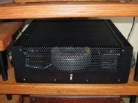
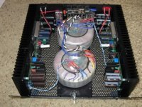
Finished up the second one. More typical layout, which works fine. Able to adjust transformer position to give low noise - no hum at speaker (100dB+).
A few have expressed concern about the complexity of the amp, and the resulting build difficulty. I would say that it not more difficult to build, just more parts to mount. The most difficult thing is matching the devices. Not too much problem with the signal or driver parts, as a battery operated jig is easy to construct, that will run them at voltages and currents something near the order of magnitude that they will see in the circuit. The outputs are a different story, because they require a lot more current. I had a problem with a couple of devices that looked close with my test (at 12V and lower current) that biased at more than double their mates, so I had to find better matches. Removing and replacing them was a pain, to say the least.
Were I to do it again, I would not solder in the output devices, but just slide them in, and use a small wire to wedge the pins snugly into the board. Then I set the bias under actual operating conditions. At this point it would be tedious, but fairly simple to switch parts.
A couple of points: Of the three parallel output parts, take the one that biases the highest and use it in one of the outside positions, as the center position will run a little hotter and bias up higher anyway. Also, check the diode voltage drop for the parts. If one is higher than the other 5, bypass that one. I had a high one, and if I used it in the bias string, I could barely get the bias low enough.
I may dress up the front with some nice wood, but here's the basic unit.
Attachments
Why not bias output transistors with assembled actual PS before putting them on board, at 35V and at their actual position on the heatsink?
That's the essence of what I propose. Since the power supply and bias circuit is assembled on the board anyway, you might as well just use it fully assembled, but with the outputs not soldered.
Sheldon
The lowest crossover distortion is when the bias voltage is about 15 to 20mV. So, ideally, they should all bias within that range. I think that if you can't get them to group that close, then it's preferable to have the lowest bias at or above 15mV, and let the outliers be higher. The limitation will be how much heat you want to accept.
Sheldon
Sheldon
- Home
- Amplifiers
- Solid State
- RMI-FC100, a single stage audio power amplifier