Since you are running the DAC directly (?) into the Sapphire, there is probably no need to have the coupling cap C1. Removing it could, I suppose, reduce some power line noise coupling since the DC impedance of the whole input section is lower. The impedance at 50/60 Hz though would be low even with the capacitor so I'm not quite sure what's going on there I admit.
Two hypotheses come to my mind:
1. Unregulated input power cables run pretty close to output singal cables. Maybe I unintentionally changed their relative positions.
2. I took measurements of unmodded board at 23:00 CEST and modded one around 01:00 CEST. Power consumption in my building must have been lower then.
Anyway we are talking about noise levels I presume I could hardly hear.
C1 takes a long time to break in as only passing a signal works .. just having the Sapphire powered up has no effect. And replacing the kit C1 with a better audio cap is also recommended.
As I said before, I played music round-the-clock for about five days before taking any critical listening. I'm not against caps in signal path per se and I could consider obtaining a better one, but I would like to hear a good argument for doing so in this particular setup. Signal from a r-2r dac ladder is delivered directly to sapphire input (there is no dc offset).
Another tweaks in queue:
1. Replace zener diodes (12V->15V) so that I could avoid signal clipping at peak volume levels when the higher gain is used. This could also provide better working conditions for opa-134.
2. Remove R2. I do not use volume pot in front of sapphire boards, and if I understand it correctly my dac posses no threat to an opamp non-inverting input. As a result I would lower dac Rload, and reduce thermal noise in the input section. Is there any other purpose of R2 that I've missed out?
No, given your setup there is no reason to use the coupling cap. It's fine without.
I recommend moving to 15 V Zeners. You have a higher V++, so you might as well make use of it. The Sapphire 3 has CSS now so the bias currents are largely independent of the voltage, just note that the power dissipation will increase in proportion to the voltage drop therefore.
re. R2, you can remove it in your case if you like, but it's not doing any harm. The DAC output impedance is assuredly low enough that it makes no practical difference having it there.
JLM Hybrid Opamp
The JLM Hybrid Opamp uses an OPA2604 which feeds an CE output stage consisting of a BD139 and a BD140. The ones used were set in Class A mode with the servo active. Offset was stable left and right at 1.2 mv.
The sound was very detailed - instruments were distinct from each other, had good overtones, and softer sounds didn't get lost. There was some intimacy.
The bass was extended. But there wasn't quite as much slam. The bigger issue, for me, was at the very high frequencies - drumstick hitting tophat and close to the center of cymbals. It was flat - like there was dampening on them or that some air was missing.
It was somewhat odd as fade away echos on vocals could be clearly heard. electric piano was clean, and drums, in general were detailed.
I've read that the OPA2604 really likes higher voltages - +/- 20 Vdc up to it's normal range of +/- 24 Vdc.
Given the cost, $23 USD, it might not be worth it. Though it might allow the use of other dual opamps, adding to the cost.
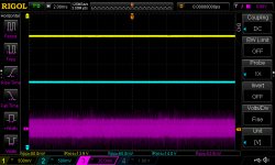
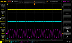
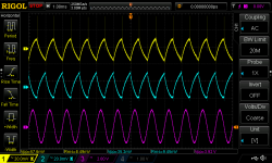
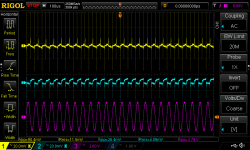
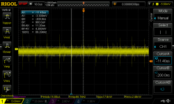
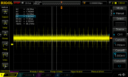
I wanted to see how V-/V+ rails behave when some input signal is applied. First I checked Vpp when no signal is produced. Then 1kHz 0dBFS sine without AC coupling and bandwidth limit enabled on oscilloscope. And afterwards with both enabled to catch details of the ripple. It look like a classical capacitor charging and discharging. What is strange: as I increase input signal frequency asymmetry arises between V+ and V- in terms of Vpp. Is this some kind of measurement error?
Attachments
I've also measured the input voltage offset of both opamps. Nominal values are quite good, given that opamps operate without any form of trimming. Only those approx. 90kHz mysterious peaks...
The measurements were done after migrating to higher V+/V- and with 15dB gain.
The measurements were done after migrating to higher V+/V- and with 15dB gain.
Attachments
I can't see any cap charging at the opamp power rails on my unit. The DC is very clean on both channels down to 10x mag of 50 mv setting using a 10x probe. FWIW - I'm using a Tek 2225 50 MHz analog scope.
Base noise on the scope is 5 mv both input and output with random noise spikes. Nothing as steady as you show.
I did build mine with different caps than what was in the kit, but that shouldn't make any difference in the measurements.
Base noise on the scope is 5 mv both input and output with random noise spikes. Nothing as steady as you show.
I did build mine with different caps than what was in the kit, but that shouldn't make any difference in the measurements.
I can't see any cap charging at the opamp power rails on my unit. The DC is very clean on both channels down to 10x mag of 50 mv setting using a 10x probe. FWIW - I'm using a Tek 2225 50 MHz analog scope.
Base noise on the scope is 5 mv both input and output with random noise spikes. Nothing as steady as you show.
I did build mine with different caps than what was in the kit, but that shouldn't make any difference in the measurements.
Did you apply 1kHz sine wave of a similar level on input during measurements? Also using 10x probe might blur a bit. What's your gain settings?
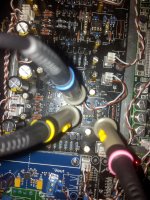
Btw - I notice in the photo of the amp, the Gnd doesn't seem to be attached. It that soldered on the bottom and run to the chassis ground point?
No, it isn't. Chassis ground is connected to earth ground. I use floating ground for all boards to avoid any complications with noise coming from neutral line and to create Faraday cage.
Did you apply 1kHz sine wave of a similar level on input during measurements? Also using 10x probe might blur a bit. What's your gain settings?
No, it isn't. Chassis ground is connected to earth ground. I use floating ground for all boards to avoid any complications with noise coming from neutral line and to create Faraday cage.
No, I have no noise when playing music. And I can clearly hear hum on the recordings that have it - it gets panned from right to left. So anything like you show on the scope trace would be audible.
Gain is 20 dB.
As for ground - I use a ground breaker. No hum, works fine. Ground runs from the boards to it and it runs to Earth ground. I was lazy and bought one of John Broskie's kits (don't see them on his web site now). Rod Elliot describes it in this article on grounding.
No, I have no noise when playing music. And I can clearly hear hum on the recordings that have it - it gets panned from right to left. So anything like you show on the scope trace would be audible.
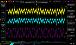
I'm not convinced whether it is the right way to do measurements as this phenomenon is obviously related to the output signal levels. Assuming that you've listened to music at 95dB SPL (which I think is quite loud) Sapphire should deliver 0.43Vrms to your HD600s; that translates to ~1.2Vpp at headphone amp output. During my tests there was ~4Vpp at input (see purple readings of Vpp), which translates to 20.3Vpp at the output. That's 25dB difference. And then there is an issue of loudness of your tracks. May I suggest using USB DAC and generate signal on PC. e.g.:
$ export AUDIODEV=hw:1,0; play -c 2 -b 24 -r 44100 -n synth sin 1000
Or if you use windows - arta software or similar. Make sure input signal is not attenuated too much.
I'm not really sure whether such drops would be audible either. We're talking about power rails, not output lines after all. But I don't feel competent enough to talk about it though.
PS. Tomorrow I will repeat my measurements.
Last edited:
Too much effort to do all the digital stuff. I hooked up my Panasonic RC oscillator - VP-7201A, set the output for 0 dB @ 1 KHz. Input on the volume pot.
As long as I stayed out of hard clipping, there was no sawtooth on the power supplies. When I went full hard clip, the sawtooth was less than 0.1 V peak-to-peak.
FWIW - hard clip is above +/- 10 Vac given the DC power at the opamp pins is just above +/- 10 Vdc.
As long as I stayed out of hard clipping, there was no sawtooth on the power supplies. When I went full hard clip, the sawtooth was less than 0.1 V peak-to-peak.
FWIW - hard clip is above +/- 10 Vac given the DC power at the opamp pins is just above +/- 10 Vdc.
Too much effort to do all the digital stuff. I hooked up my Panasonic RC oscillator - VP-7201A, set the output for 0 dB @ 1 KHz. Input on the volume pot.
And what voltages does 0dB translate to?
As long as I stayed out of hard clipping, there was no sawtooth on the power supplies. When I went full hard clip, the sawtooth was less than 0.1 V peak-to-peak.
I think I have nailed down the issue. When I repeated measurements in the manner as shown previously, I got the same results. Then I decided to stick input signal probe to the second board and it turned out the order of magnitude of ripple was lowered by 1. Using only one channel of the oscilloscope (to rule out crosstalk at that device) didn't bring any significant improvement.
FWIW - hard clip is above +/- 10 Vac given the DC power at the opamp pins is just above +/- 10 Vdc.
Power rails in my case enjoy higher voltages (~14V). I've replaced zener diodes.
Attachments
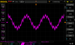
Speaking about grounding and ground breakers... This is what can be seen between earth and neutral lines at randomly selected power plug in my home. Data gathered at midnight or so.
PS. Just to be clear: not that I'm questioning using proper grounding at power amps.
PS. Just to be clear: not that I'm questioning using proper grounding at power amps.
Attachments
FWIW - 0 dB - 1 V into 600 ohms. Most older test equipment is calibrated to the old standards. Consumer audio -10 dB, Pro audio +4 dB are the reference levels.
As for noise on the power line, sure that's pretty common unless one is running off-grid using a crystal generated sine wave supply from an inverter. But a refrigerator on the same circuit will destroy that clean power pretty quick
Consider though that if the Gnd on the Sapphire isn't used, where are the diode pulses going to leak into? They aren't going to stay in the small area between the diode bridge and main power caps. Without a path to ground, they'll find a path to ground. Even if it's using signal ground to get there.
@forta + disfunctionalshadow
The Zreg output V+ and V- will have minimal ripple. I doubt you'd see it in the scope trace unless you used a bandpass filter. I can't remember off the top of my head what it should be, but 5 mV p-p seems about right. (Zreg cuts about 40 dB from V++, and V++ has 2000 uF per rail per channel.) It will vary a little with the current draw of the circuit of course, so a large input signal or unusually large output bias current will cause the ripple to increase slightly.
The Zreg output V+ and V- will have minimal ripple. I doubt you'd see it in the scope trace unless you used a bandpass filter. I can't remember off the top of my head what it should be, but 5 mV p-p seems about right. (Zreg cuts about 40 dB from V++, and V++ has 2000 uF per rail per channel.) It will vary a little with the current draw of the circuit of course, so a large input signal or unusually large output bias current will cause the ripple to increase slightly.
New Chesky Bi-naural Headphone Demonstration Album
Sorry if this is a bit off topic, but I wanted to pass it along.
I just got my hands on a copy of this cd. The sound - using Sapphire and Sennheiser hd-600s - is impressive and notable- 3-D imaging is very real. I think this was recorded for headphones as it sounds unimpressive played through stereo speakers.
What's wrong with BC337/327?
Yes, I recommend them. Combination of availability and fitness for the purpose.
OK. I had thought of something like 2sc2240 / 2sa970 but anyway ...
")
1 - What is the ideal voltage amplitude on the load? Or varies the power you want? Ex: 6v amplitude / 60 ohms load.
The higher the amplitude of the load, will have more definition / fidelity?

- Home
- Amplifiers
- Headphone Systems
- RJM Audio Sapphire Desktop Headphone Amplifier