Hi Richard, if I want to increase gain in Rev14, can I just parallel R8 to reduce the value instead of changing R8. its much easier. Is there any particular reason for selecting the value of R7 to be 4.7k in the first place, why not 5k? (// R8 1k with 4k = 800R, so 4.7k/800R +1 = 6.875)
In the old version of the circuit the gain is set as R7/R8+1 i.e. 1/4.7+1=~6 There's a number of factors which influence the resistance values you'd want to pick, but as long as you keep R8 between 500-1500 ohms, and R7 say 3k~30k you won't run into any problems.
The actual BOM values are chosen to 1. give the optimum gain with the widest range of headphones and 2. nominally balance the input impedances at audio frequencies. 3. keep the total resistance of the feedback loop above 5 k or so to avoid loading the op amp.
The actual BOM values are chosen to 1. give the optimum gain with the widest range of headphones and 2. nominally balance the input impedances at audio frequencies. 3. keep the total resistance of the feedback loop above 5 k or so to avoid loading the op amp.
Last edited:
Richard, I read somewhere that mentioned the "rule of thump" with respect to the input resistor and volume pot whereby the input resistor should be 10x greater than the volume pot. I am using 10K Alps RK097 in my Sapphire V14s, not because I am following the rule but I only have 10k and 50K Alps RK97. I am happy with the present setup. Since I have Alps RK97 Blue Velvet lying around and it is definitely better than RK097. Is it ok if change to 50K pot without changing the input resistor R6 from 100k to 500k.Thanks.
Leaving it at 100k wouldn't be a major issue.
Note that the maximum source impedance provided by a 50k pot is 12.5 kOhms, which would affect AC impedance balance. The OPA134 datasheet mentions that unbalance at the inverting and noninverting input terminals better be no greater than 2 kOhms. Like many FET input opamps, it has rather high imput impedance distortion at high frequencies, which can be nulled out by careful impedance balancing.
(Imbalance in DC resistance plus full gain at DC also is why the NE5534 with its substantial input bias current gave high output DC offset in this circuit.)
Yep. The input section is optimized for impedance balance of the inputs at audio frequencies rather than for DC.
To clarify the issue of volume control impedance, 10k, 20k or 50k won't make much of a difference to anything and there is no need to adjust the resistance values to compensate.
If anyone is interested, the input stage assumes the typical impedance of the volume potentiometer as seen from the op amp is 500 ohms. That calculation was based on my 50k Takman stepped attenuator and my normal listening level. The instructions call for a 20-50k value. That specification is a usual compromise between too large (noisy, distortion) and too small (excess loading of the input signal).
Thanks guys. If 20k-50k is recomended, then I will try the Alps Rk27 50K. I hate to order from ebay when there is some many fake Alps in the market especially sellers from China. And element14 Malaysia is charging exorbitantly high price for Alps pot.
Btw, have anyone tried opa227, I like it better in Cmoy amp than opa134.
Btw, have anyone tried opa227, I like it better in Cmoy amp than opa134.
I took Richard's advice yesterday. I opened up my sapphire and resolder all the components especially the gain resistors, clean the board with alcohol, soap and water. Wipe clean and dry overnight. Today I reassembled and check DC offset. Both channels reduced to -2.7mV and 3.5mV for left and right respectively. Before it was 35mV and 10.5mV.
I also increased the gain to about 7.5. Now I like it better with my DT880 600ohms. I don't have to turn to max when using my Galaxy N3 as a source. I love my sapphire from the first day I had two yrs ago and I still love it today. I wonder how much better is the currernt version?
I also increased the gain to about 7.5. Now I like it better with my DT880 600ohms. I don't have to turn to max when using my Galaxy N3 as a source. I love my sapphire from the first day I had two yrs ago and I still love it today. I wonder how much better is the currernt version?
Hi Richard,
I have the 1.4s1 and I'd like to try it as per 2.0 revision.
Could you give me the info about that?
Frank
I have the 1.4s1 and I'd like to try it as per 2.0 revision.
Could you give me the info about that?
Frank
Hi Fran, I was just about to email you on this subject. The downside of the transplant is the old version is no longer available for me to compare to, so I was planning on hitting you up for your evaluation of 14s1.
The circuit sounds a bit "gummy" for the first 2-3 days until the electrolytic capacitors shake themselves out. So my impressions of 20f will have to wait until the weekend.
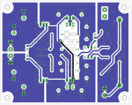
While the 14s1 boards can be modified, it is not trivial: you'd have to cut traces on both the top and bottom of the boards, and wire resistors between pads to connect over the cut traces. If you are up for it I can show you what and where.
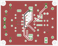
Red is the top trace, blue is the bottom. X-ray view.
Black traces between Q3 and R10, and Q4 and R11, must be cut, and 1 ohm resistors to bridge the cut trace, connected to the pads marked in black circles.
Increase R10,11 from 330 ohms to 1 kohm.
/R
Black traces between Q3 and R10, and Q4 and R11, must be cut, and 1 ohm resistors to bridge the cut trace, connected to the pads marked in black circles.
Increase R10,11 from 330 ohms to 1 kohm.
/R
Attachments
Good luck. Remember that the voltage across R13 and R14 tells you the bias current, as I = V/R. If should be about 30 mA for best results, and you can adjust by changing the value of the resistors you add over the cut traces.
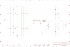
Which should be about 4.7 ohms, I realized, not 1 ohm as I wrote above. Sorry about that! (you are adding R9, R10 from the rev 2.0 schematic, below)
Which should be about 4.7 ohms, I realized, not 1 ohm as I wrote above. Sorry about that! (you are adding R9, R10 from the rev 2.0 schematic, below)
Attachments
Good question. It tells me you are serious about this...
I do not know what the ideal value for the emitter resistors is, for a given bias current. The general rule for (power) amplifiers is 0.47 ohms for 30 mA. I doubt there is a material difference between 1 ohm and 0.47 ohm, but it does influence the bias current. So if you stick with 0.47 ohms, you might find the bias current is a little higher than 30 mA when you use 4.7 ohms for the bias trim resistors (R9,10 rev 2). Maybe lowering the trim resistors to 3.3 ohms or 3.9 ohms would be better in that case.
/R
Hi, RJM, Pending the arrival of a proper enclosure, I mounted the Sapphire into an old metal cookie box, just to make sure I understood things well enough to put together a working amp. With the overly long wires, it looks a bit like a bowl of twisted-pair spaghetti.
In any case, it's all wired up. I was checking the voltages and found most values were close to the recommended ones. I did want to check two values with you though. When I measure the voltage across Out+ and Out-, the value is negative (-20 mV on one channel and -16 mV on the other). Does that indicate a problem of some sort? And the voltage difference between In+ an In- measures 105 mV and 150 mV on the two boards, not zero. Is this problematic?
In any case, it's all wired up. I was checking the voltages and found most values were close to the recommended ones. I did want to check two values with you though. When I measure the voltage across Out+ and Out-, the value is negative (-20 mV on one channel and -16 mV on the other). Does that indicate a problem of some sort? And the voltage difference between In+ an In- measures 105 mV and 150 mV on the two boards, not zero. Is this problematic?
Hi!!
Just finished the discrete opas but... don't work! ... I must to recheck all
I have change the rectificator bridges, change all screws, make a box... ;-)
I will put a braided sleeve in wires and change the on-off button.
Probably I will change the russian capacitors for a Clarity Caps, Mundorf or Jupiter
After a weeks of burn-in a lot, the amp sounds incredible.
It move very well the LCD3 and the HD800. Not as good as a Beta22, but the Sapphire it's a "Burson Killer", very very great sound for the price.
If you wan't to follow the project with more photos, here is the post ( In spanish ;-) )


- Home
- Amplifiers
- Headphone Systems
- RJM Audio Sapphire Desktop Headphone Amplifier