that right one
Thanks, ZM. I'll do it tomorrow.
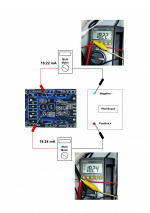
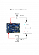
Those measurements confirm that 0.02mA are exiting the circuit by another route.Hi ZM, I have 18.22 mA and 18.24 mA on the board with the mosfets removed.
That other route is probably the Power Ground to PSU Zero Volts.
Whereas post99 (left pic) shows 0.28mA exiting by another route. That big ground current probably indicates a fault.
Last edited:

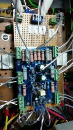
well , if mosfets are not having mixed pin wires , and if they're good ...... I can't see anything wrong
though - I'm not having capture of top and bottom copper of PD boards , so I can't say which mosfet position(s) are alive , meaning - of which mosfet position is source resistor monitored in Aleph CCS
if you're sure that all 4 mosfets are well and alive - connect them all
connect that pcb exactly in same manner as functional pcb , for now
sorry - we are running in circles .......
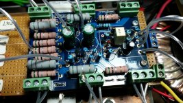
- according to measurements in #106 - input LTP is functional ;
- recheck all resistor values in Aleph CCS area ( positive side of output stage)
-in fact - recheck all resistors (easier to say that , than to list them by function )
- while doing that , re-check all soldering joints
- if you're sure that mosfets are OK (consult mosfet testing article from FW site, how to properly test them ) , connect them all
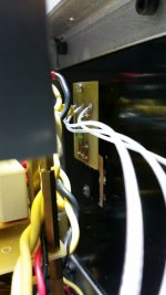
- connect all wires in exactly same fashion as on functional channel
- fire it up ; check output offset and Iq ; best place to check Iq is measuring voltage across one of source resistors in negative output stage side (those connected to negative PSU rail)
- according to measurements in #106 - input LTP is functional ;
- recheck all resistor values in Aleph CCS area ( positive side of output stage)
-in fact - recheck all resistors (easier to say that , than to list them by function )
- while doing that , re-check all soldering joints
- if you're sure that mosfets are OK (consult mosfet testing article from FW site, how to properly test them ) , connect them all
- connect all wires in exactly same fashion as on functional channel
- fire it up ; check output offset and Iq ; best place to check Iq is measuring voltage across one of source resistors in negative output stage side (those connected to negative PSU rail)
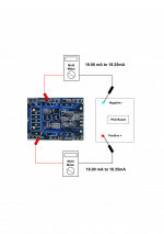
that difference of over 6mA must be exiting via another route, probably to the PSU Zero Volts.I have removed inputs off the gnd and connect and it is now the same as the functional unit. Attached is the measurement. I do not know why is the positive rail differs so much from the negative rail.
Thanks, ZM. I appreciate your help.
Measure it and confirm you know where the current is going.
- Status
- This old topic is closed. If you want to reopen this topic, contact a moderator using the "Report Post" button.
- Home
- Amplifiers
- Pass Labs
- Rising DC Offset