Raise C3 (like triple) and/or lower C2 (like 10-25%) in value. See where that gets you. Once you get the bass sounding better put a small value (20-50 ohm to start) resistor inline with C4 to get the highs singing.
Use your ears and double check with meters.
I tried increasing C3 (the coupling cap) to 0.68uf but that had little effect. I then dropped C2 from 51.7nf to 47nf. That made things much worse. In the sub 100Hz portion of the audio band, in now way below the RIAA curve.
I don't know what to suggest on this. The circuit itself wouldn't seem to be at fault.
Phono preamps and RIAA specs are something alien to me but I believe the RIAA was changed in the 80's ? Does that affect the encoding as well as the decoding ? Could you be chasing a non existent issue here.
Here is a clearer image of the set up as well.
I thought about that. The response I'm getting below 100Hz doesn't follow either the pre-1980's curve or the post 1980's curve.
I've used google to find some formula's for calculating a passive RIAA based on the pre 1980's curve and my calculations give me similar values for R7, R8, C2 and C4 compared to the circuit. This is good because your model also uses the same circuit values and delivers the expected RIAA frequency response. Somehow the actual circuit doesn't agree with us!
")
I'm now at a total loss about what to try next.
Doesn't make sense. Did you re-reference 1khz to 0db before checking low freq roll off? Are you listening to the circuit after changes?I then dropped C2 from 51.7nf to 47nf. That made things much worse. In the sub 100Hz portion of the audio band, in now way below the RIAA curve.
Last edited:
I agree, it doesn't make sense... yes, i referenced to a newly measured 1kHz each time. Both channels measure similarly.
All my measurements are via my HP oscilloscope. I haven't bothered to hook it up to my turntable yet given the very poor sub 100hz measurements. I must have simple error in my build. Either that or it really is a poor circuit.
All my measurements are via my HP oscilloscope. I haven't bothered to hook it up to my turntable yet given the very poor sub 100hz measurements. I must have simple error in my build. Either that or it really is a poor circuit.
Disconnect the compensation network from the output of the first stage and determine it's impedance. This will let you know what value you should use as the build-out resistor.
Great idea!
Perhaps the BC549 transistors perform differently to BC109's??
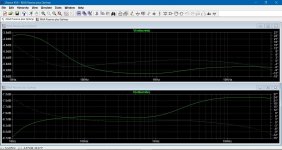
The simulation shows that different transistors do have an effect, and tbh that is never a good sign in what should be fairly generic circuitry. This shows the effect of using 2N5550 devices which are a standard small signal NPN device.
BC547C at the top, 2N5550 at the bottom.
BC547C at the top, 2N5550 at the bottom.
Attachments
All you can do is try it and it would be interesting to compare the real vs simulated. I don't like the way the basic design is so transistor dependent (whether or not it fixes your issue). Things like gain differences (of the completed amp) are not good to see.
A design like this should really work with pretty much anything you throw at it.
A design like this should really work with pretty much anything you throw at it.
the BC 546, 547, 549 and 550 are all very alike.I will have to track down some BC547's to see if the circuit matches your original simulation.... Will be weekend job as my day job is very busy right now.
The 549 and 550 are specified as low noise.
The 546 and 550 are specified as higher Vce0
they all come in ungraded (more likely to be fakes), a, b, or c
Buy a bc550c for Vce0 @ 45V and Gain >400 and easily available.
I would drive R7 from low impedance, same circuit as Q5 placed in Q1 collector.
That's not a bad idea! I'll try it this weekend and let you know how it worked out.....
Hi Mooly,
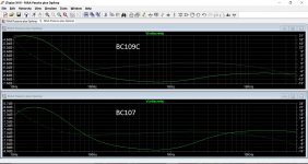
Would you be kind enough to re-run the spice model with BC109c transistors in it?
Thank you!
I haven't got models for the BC109C although other high gain devices should give similar results.
I'm spiceless today, just on a tablet and so can't run any sims- hopefully tomorrow or Saturday.
Ok here's an update...I can't get bc109 transistors easily so I grabbed some bc457's to see if I could replicate the results Mooly got with bc547's.
I seem to get the same real world results with either BC549 or BC547 transistors. In other words, I don't get the response curve Mooly gets.
This is good and bad. Good: the circuit performance doesn't appear to be transistor specific; bad: I still have poor bass response
I seem to get the same real world results with either BC549 or BC547 transistors. In other words, I don't get the response curve Mooly gets.
This is good and bad. Good: the circuit performance doesn't appear to be transistor specific; bad: I still have poor bass response
- Status
- This old topic is closed. If you want to reopen this topic, contact a moderator using the "Report Post" button.
- Home
- Source & Line
- Analogue Source
- RIAA Help