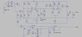
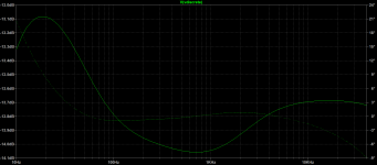
Here is the same circuit but with a different inverse RIAA network. It still follows the same basic curve as before.
I think you need to look closely at both my simulated circuit (to make sure I haven't made a silly mistake with a component value) and also at your real circuit, again making sure the parts really are agreeing between the two.
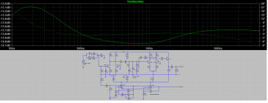
I've attached the details of the inverse RIAA as well.
I think you need to look closely at both my simulated circuit (to make sure I haven't made a silly mistake with a component value) and also at your real circuit, again making sure the parts really are agreeing between the two.
I've attached the details of the inverse RIAA as well.
Attachments
Thank you Mooly, I appreciate your help.
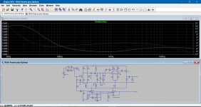
The version on the test bench now has a few components slightly different to your simulation circuit. The differences are:
R1 – 8k
C1 – not installed yet
R4, R5, R14, R15 – all now 315R
My PSU is +24v and -8v
Transistors are currently BC547 in one channel and BC549 in the other. Frequency response performance is almost identical between the channels.
Other than that, everything else is identical to your simulation circuit.
- Status
- This old topic is closed. If you want to reopen this topic, contact a moderator using the "Report Post" button.