Wakibaki, Macboy
I was expecting a bit more strong reasoning..
This way is too easy..
So we could see that reflections are easily detectable even in a more or less reasonably configured setup.
And these reflections are much attenuated, with respect to the signal itself, by an inserted attenuator.
Previously it was not possible for You, now it does not matter, because of the timing.
You want something much more obvious? Just change the cable. In this small world of ours, we all are using the same digital cables, aren't we?
I really would have expected from you to realize that if reflections are there, then their position will depend on the setup!!
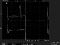
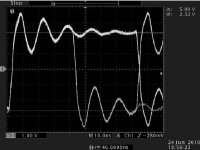
The setup otherways is the same like before, in every aspect. I have adjusted the generator to respect the bit timing of a 192 khz spdif signal.
That smaller perturbation BEFORE the main reflection is the secondary reflection from the previous edge!
Second trace is with attenuator.
Last word: padding is an age old engineering trick, look up phase noise documentation from Nist, where they were aiming for really low jitter measurements.
I was expecting a bit more strong reasoning..
This way is too easy..
So we could see that reflections are easily detectable even in a more or less reasonably configured setup.
And these reflections are much attenuated, with respect to the signal itself, by an inserted attenuator.
Previously it was not possible for You, now it does not matter, because of the timing.
You want something much more obvious? Just change the cable. In this small world of ours, we all are using the same digital cables, aren't we?
I really would have expected from you to realize that if reflections are there, then their position will depend on the setup!!
The setup otherways is the same like before, in every aspect. I have adjusted the generator to respect the bit timing of a 192 khz spdif signal.
That smaller perturbation BEFORE the main reflection is the secondary reflection from the previous edge!
Second trace is with attenuator.
Last word: padding is an age old engineering trick, look up phase noise documentation from Nist, where they were aiming for really low jitter measurements.
Attachments
Repeating yourself, Joseph K, doesn't make your case any more convincing.
I notice anyway, that you have deliberately chosen not to show the low level trace (i.e, it's off-screen), which makes it impossible to tell what vertical amplification you are applying to get these traces to look the way they do.
This is cheating. It only serves to weaken your case.
Even taking the bottom of the screen as the low level of the trace these little twitches will wash right past a PLL. It will ignore them. They are insufficient to be mistaken for data transitions, even though you have chosen to create a mismatch specifically to exaggerate them. It is extremely unlikely they will be as pronounced in normal operating conditions.
Jitter is specifically the movement of rising and falling data or clock edges around their mean position.
If the reflections were impacting on the positions of the rising and falling edges then there might be some merit to your argument, but your traces clearly show the spacing between the rising and falling edges to be unaffected, and the edges themselves to be clean and pronounced. Although obviously this is only the spacing, it is a good indicator that the repetition rate is unaffected, and it is difficult to see how the positions of the rising and falling edges could in fact be affected by reflections on the line.
I fully appreciate your desire to discover something that you can share with us, but please appreciate that your unmoderated enthusiasm is, in this case, leading you to a completely unjustified and erroneous conclusion.
w
Wakibaki,
In the first graph I have shown the full amplitude. Then I said I'm showing again the same with high resolution. Now I said I'm repeating the same setup, which means in my vocabulary, that it is the SAME, full amplitude included.
Could You please show me where is it that I am cheating? Or is it You who is not reading?
The timing: You said it does not have an influence on the edges. It's in your right to conclude as You wish. It will not change the real nature of the things. Now I had shown just another cable, and it strongly changed the timing. Now shall I get up and search the third cable which will just bump even the main reflection right on the bit timing edge? And we are not talking about the secondary and other reflections. And about the fact that bit timing is a function of the transmission speed, and the data content? So how can You be so sure of what falls where?
Ciao, George
Just another point: when You had been measuring the line termination load by a multimeter, and it came out (at DC) 75ohm, how could You be so sure that it was fitting the line impedance?
In another words, could You please show me how to measure the REAL characteristic impedance of the line with a multimeter?
Maybe You could teach me something here.
In another words, could You please show me how to measure the REAL characteristic impedance of the line with a multimeter?
Maybe You could teach me something here.
Just another point: when You had been measuring the line termination load by a multimeter, and it came out (at DC) 75ohm, how could You be so sure that it was fitting the line impedance?
In another words, could You please show me how to measure the REAL characteristic impedance of the line with a multimeter?
Maybe You could teach me something here.
Yea, Wakibaki, I'd love to know too - please share we want to learn - it would stop all this erroneous stupidity that is misleading the gullible hoard.
Last edited:
[snip]The setup otherways is the same like before, in every aspect. [snip].
Joseph,
To be honest, I have a hard time to see any change in the timing (rise/fall time) of the two cases. Did you do any measurements of that, any numbers?
jd
So you Diss someone that one have some science to backup his stories (those stories he/she told about lenght they are true only in open air). when he/she doesn't agree with you. you put those insignificant scope pictures and scream that now smoother signals you get with attenuation. You must be read some docs otherwise you can't get it all so wrong. Meaning you have only one spdif signal and it is relatively slow and you can generate jitter with it. Oh i almost forget that you said that wakibaki knows everything and you like to learn more so why don't you learn basic digital electronics OR AT LEAST WHAT JITTER REALLY MEANS. You said that he/she should be more open minded and accept new Ideas. there is already term for that it's called science fiction.
So you Diss someone that one have some science to backup his stories (those stories he/she told about lenght they are true only in open air). when he/she doesn't agree with you. you put those insignificant scope pictures and scream that now smoother signals you get with attenuation. You must be read some docs otherwise you can't get it all so wrong. Meaning you have only one spdif signal and it is relatively slow and you can generate jitter with it. Oh i almost forget that you said that wakibaki knows everything and you like to learn more so why don't you learn basic digital electronics OR AT LEAST WHAT JITTER REALLY MEANS. You said that he/she should be more open minded and accept new Ideas. there is already term for that it's called science fiction.
Sorry, I have a hard time to understand your post, there seems very little substance in it but you seem to imply that you know about this stuff? Maybe you can explain to us how it really is? That would help us all.
jd
Hi all, and specially Jan ")
Pardon me, it's meeting time here and my time is scarce..
Though it was not bad at all for me to set back and relax, things are clearer observed from a distance.
Here I am accused of arriving at false conclusions while I was angry because I smelt "simplification" lurking in the bush and pushing others to arrive at wrong conclusions, from my point of view..
Some things to clear above all:
First, we are talking about subtle things here. Subtle shifts in the timing at the decision point at the receiver side. We are talking about dozens / at max hundreds of picoseconds. Nobody said that this compromises SPDIF data protocol. These shifts are influencing clock recovery at the receiver.
Then, Gmarsh was putting all this in the right light, which is really important:
I would discuss about attenuators ONLY in the special case of one special device, the Hiface driver. Because (at least for now) it is the only one which permits to attenuate without compromising the standard levels at the receiver; and because it is fast enough to bring up the problem of reflections.
The main point what wakibaki is missing is: SUPERPOSITION. If my original signal creates a series of reflections in the line, this newly created signal will add up to the original. In each and every moment, also those few nanoseconds during the transition. It will not go up / down like a straight line anymore, it will be distorted, "waving" around the ideal slope. This makes it arriving sooner/ later to the decision point defined in the receiver.
Also, the top & bottom part of the signal is not flat, in more ways.
It has noise on top of it;
It has "droop", the "angled" deviation caused by the high pass elements introduced in the line. The amount of the level shift is data related!
If the rise /fall times were infinitely small, that is vertical transition, than neither the noise, neither the droop would not be a problem. But the transitions are far from vertical, they are finite even in my demonstration setup, and they are much higher, sometimes as much as 30 nsec in real life. In our special case, the HIface, they are 2nsec.
At bit transition time, this means ideally a "slope" launched by the driver. The signal does not arrive to the decision point, until this slope crosses the level fixed by the decision point.
If this slope is "wriggled" (noise from reflections), that makes it arrive sooner /later.
If this slope starts from higher/lower because of the noise & droop (data!) on the top/ bottom, will again arrive later/ sooner.
If this slope in the same time is also wriggled, than shifting up/down the wriggles will contribute to additional time shifts.
Ciao, George
Last edited:
OK, post a before and after attenuation screenshot showing the reduction in jitter (i.e. reflections coincident with the rising or falling edges), rather than just some 'wriggles' in the high level of some pulses...
Oh, and an explanation of how you can tell when reflections ARE coincident with rising or falling edges (preferably using a multimeter).
w
Oh, and an explanation of how you can tell when reflections ARE coincident with rising or falling edges (preferably using a multimeter).
w
Why don't you tell us what you understand from the shots you are seeing - from an engineers perspective & tell us how to use a DMM properly - I didn't know I could do the things you suggest with a DMM. I'm saying this in a genuinely open way & not being sarcastic - You seem to be a knowledgeable guy - I'm willing to take on new information!OK, post a before and after attenuation screenshot showing the reduction in jitter (i.e. reflections coincident with the rising or falling edges), rather than just some 'wriggles' in the high level of some pulses...
Oh, and an explanation of how you can tell when reflections ARE coincident with rising or falling edges (preferably using a multimeter).
w
Hi all,
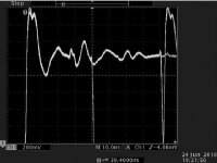
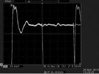
By the way, this what it looks like a Hiface driver connected directly (with a BNC "I" )
to the scope input. A USB extension cable is used for the laptop.
But be careful! The second shot is what it looks like when this "no SPDIF cable" is not terminated well..
By the way, look at the edges, and tell me that they are a strait line.
Exactly this is what happens with the smaller "wriggles" in the previous shots, only much harder to show, because of the proportions.
Ciao, George
P.S.: Compare this "nice" direct shot to the cable+attenuator one.
The small "wriggle' which is left in the middle in both shots, is not a reflection, a perturbation on the driver output.
Attachments
Last edited:
Right, taking the first post, what I see is 2 images, one entitled 'RF-Attenuators = Jitter Reducers-hiface_noatt_hires', and the other 'RF-Attenuators = Jitter Reducers-hiface_att_hires'. Both show traces with virtually identical rising and falling edges, although they're difficult to interpret because both seem to show an overlaid falling edge about halfway along the pulse, but since they both show this artifact, this cannot be the effect we are looking for. The image without the attenuator shows more overshoot and ringing than the one without, but neither show anything significantly different from the traces already presented. Again, the full trace is not shown, why the low level is not shown I can only guess, since I complained about this omission in earlier posts.
The second post shows two images which I am completely at a loss to interpret, since the accompanying text is close to incoherent. I appreciate that English may not be the poster's first language, but a clearer explanation of exactly what is supposed to be being shown is necessary if any real meaning is to be conveyed.
If you cannot make your meaning clearer I will cease to correspond with you entirely. With regard to this, I suggest that matters are not being improved by your obvious loss of self-control. In any case I am not about to be impressed by somebody getting annoyed a very long way away, so please don't SHOUT.
As far as not liking the tone is concerned, all I have done is mirror back to you the tone of your earlier remarks, where you suggested to me that I should explain to you how to measure the characteristic impedance of a cable using a multimeter, a remark sarcastically echoed by jkeny.
This example of ill-manners is probably representative of the behaviour which led to his being banned elsewhere. His protestations...
'I'm saying this in a genuinely open way & not being sarcastic'
...simply make this more likely. He must think I (and any other readers) came down with the last shower of rain. But we knew that anyway.
w
I agree I was being sarcastic when I suggested this but now I am genuinely interested - if it is possible I would like to know the technique!Right, taking the first post, what I see is 2 images, one entitled 'RF-Attenuators = Jitter Reducers-hiface_noatt_hires', and the other 'RF-Attenuators = Jitter Reducers-hiface_att_hires'. Both show traces with virtually identical rising and falling edges, although they're difficult to interpret because both seem to show an overlaid falling edge about halfway along the pulse, but since they both show this artifact, this cannot be the effect we are looking for. The image without the attenuator shows more overshoot and ringing than the one without, but neither show anything significantly different from the traces already presented. Again, the full trace is not shown, why the low level is not shown I can only guess, since I complained about this omission in earlier posts.
The second post shows two images which I am completely at a loss to interpret, since the accompanying text is close to incoherent. I appreciate that English may not be the poster's first language, but a clearer explanation of exactly what is supposed to be being shown is necessary if any real meaning is to be conveyed.
If you cannot make your meaning clearer I will cease to correspond with you entirely. With regard to this, I suggest that matters are not being improved by your obvious loss of self-control. In any case I am not about to be impressed by somebody getting annoyed a very long way away, so please don't SHOUT.
As far as not liking the tone is concerned, all I have done is mirror back to you the tone of your earlier remarks, where you suggested to me that I should explain to you how to measure the characteristic impedance of a cable using a multimeter, a remark sarcastically echoed by jkeny.
Ok, let's all calm down - I was reacting to your attack on me saying that I was spreading mis-information & casting a slur on professional designers - it was very much an attack on me as far as I was concerned & you haven't let up - remember you attacked me out of the blue & I reacted - but let's put this in the past now.This example of ill-manners is probably representative of the behaviour which led to his being banned elsewhere. His protestations...
I sincerely hope you can stop attacking me - I don't mean any bad intent. I started this thread to offer what i thought might be useful information to Hiface users & hoped some would experiment with a $12 purchase & report their findings. You stomped all over this like I was the devil incarnate & this thread became all about substantiating my statement.'I'm saying this in a genuinely open way & not being sarcastic'
...simply make this more likely. He must think I (and any other readers) came down with the last shower of rain. But we knew that anyway.
w
I really want to get back to the thread's original intention if that's possible at this stage & let some other people have a vote in whether this is a worthwhile thing to do! What's the harm in this?
If you suspect my intentions, there's little I can do
Last edited:
So please, if anybody has tried this on their Hiface, please don't be afraid to post your results here, positive or negative - I'm just interested in how this works for others. Don't worry, you won't be asked to present scope plots or engineering reports - your listening impressions will do
Wakibaki,
You asked me:
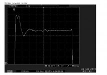
So I did it, the first shot shows the reflection in the line "coincident with the falling edge", the next shot, with attenuator applied shows this reflection decreased.
That strange thing,
is exactly what you asked for, the overlaid falling edge of a bit transition, you know, the mid cell level transition representing a logical "1" in the bi-phase mark II encoding.
When there is a zero, the cell does not change status, and the DPO screen shot (Digital Phosphor Oscilloscope, look it up) does show the overlay of all these states.
Anyway, these shots clearly demonstrate that in this line the transitions sometimes clearly happen right in the middle of the perturbation caused by the reflection.
The other shots were not for You. I hope that the people who might be interested in them, will somehow get it.
Finally, I would like to make it very clear that it was You who brougth up the idea of cleaning up an SPDIF transmission line by the help of a DMM:
quote from wakibaki, post 19:
I have only pointed out, that for right termination you should know the line characteristic impedance, the real one, not the declared one.
You asked me:
OK, post a before and after attenuation screenshot showing the reduction in jitter (i.e. reflections coincident with the rising or falling edges)
So I did it, the first shot shows the reflection in the line "coincident with the falling edge", the next shot, with attenuator applied shows this reflection decreased.
That strange thing,
because both seem to show an overlaid falling edge about halfway along the pulse
is exactly what you asked for, the overlaid falling edge of a bit transition, you know, the mid cell level transition representing a logical "1" in the bi-phase mark II encoding.
When there is a zero, the cell does not change status, and the DPO screen shot (Digital Phosphor Oscilloscope, look it up) does show the overlay of all these states.
Anyway, these shots clearly demonstrate that in this line the transitions sometimes clearly happen right in the middle of the perturbation caused by the reflection.
The other shots were not for You. I hope that the people who might be interested in them, will somehow get it.
Finally, I would like to make it very clear that it was You who brougth up the idea of cleaning up an SPDIF transmission line by the help of a DMM:
quote from wakibaki, post 19:
ALL that is required is a 75R resistor across the line at the receiving end. You CAN just measure it with an ohmmeter.
I have only pointed out, that for right termination you should know the line characteristic impedance, the real one, not the declared one.
Last edited:
- Status
- Not open for further replies.
- Home
- Source & Line
- Digital Source
- RF Attenuators = Jitter Reducers