The assumption was that the mismatch was at the receiver end termination, and the attenuator pad would be placed just before that end termination. That would be just before the DIR I guess.
I agree that there are a lot of buts and ifs, but the mecahnism seems to be there.
BTW There are a lot of DIR's that can handle both AES/EBU signales and S/PDIF signals. These are almost identical (except for a few status bits) but AES/EBU is about 6 or 7 times higher in voltage level than S/PDIF. So an attenuator in such a case in an AES/EBU link would have little effect on the receiver, but the S/PDIF voltage level may become too low.
jd
It's hubris, foolish pride, to imagine that you can come along with a $12 device and improve perceptibly on the performance of a device constructed by experts.
Some strange new meaning of 'experts' which includes people who can't or won't read the SPDIF spec...

I'm leaving you guys to it - arguing about how many angels fit on the head of a pin is pointless. All I can say is read the datasheets, have a look at the TDR plots & think - although those who know it all need not do this as they have learned everything there is to learn! Me I'm still learning & hope I never stop - I fear the smell of stagnation might overwhelm me.
Last edited:
The point is that if you put a T-pad, or H-pad, correctly designed for 75Ohm termination (on both sides! You create a new source for 75Ohm lines with a weaker signal), at the end of the line you still have the potentially wrong terminated end in the receiving entity. You have an attenuated signal AND still remain with reflections from the wrong terminated receiver. That sounds even worse to me.
IMHO...Just go and fix that input to have the correct termination, use 75Ohm BNC on RG59, thats what the engineer would do. Maybe you want to coat it with C37 to feel better (sorry... sarcasm)
Br
Josch
IMHO...Just go and fix that input to have the correct termination, use 75Ohm BNC on RG59, thats what the engineer would do. Maybe you want to coat it with C37 to feel better
(sorry... sarcasm)Br
Josch
to all those clever theorists
Ok.
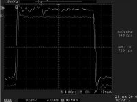
Here it is the difference before / after the insertion of an attenuator into a deliberately "wrongly" terminated 75ohm transmission line.
the setup is:
Upper trace
generator - 75ohm line - BNC tee (real 75ohm) - 75ohm termination.
The BNC tee goes into the 1Mohm input of my scope.
Lower trace
generator - 75ohm line - 10dB 75ohm attenuator-BNC tee - 75ohm termination
The BNC tee goes into the 1Mohm input of my scope
As you see, the only diffeence is the attenuator. The traces are normalized, so as to see the same percentage of the reflections.
I did not put up here the Hiface driver, because:
-I do not intend to discuss about it's output waveform
-I've put it on Diyhifi.org, please go and see.
The driver used is a 250MHz Hp pulse generator. The rise & fall times, ~700psec are limited by the scope.
The Hiface is only slightly worse, 1.8nsec rise time.
Last but maybe most important note: I show this setup & graphs again and again, because EXACTLY THIS IS the difference what your dac sees on it's input.
Ciao, George
Ok.
Here it is the difference before / after the insertion of an attenuator into a deliberately "wrongly" terminated 75ohm transmission line.
the setup is:
Upper trace
generator - 75ohm line - BNC tee (real 75ohm) - 75ohm termination.
The BNC tee goes into the 1Mohm input of my scope.
Lower trace
generator - 75ohm line - 10dB 75ohm attenuator-BNC tee - 75ohm termination
The BNC tee goes into the 1Mohm input of my scope
As you see, the only diffeence is the attenuator. The traces are normalized, so as to see the same percentage of the reflections.
I did not put up here the Hiface driver, because:
-I do not intend to discuss about it's output waveform
-I've put it on Diyhifi.org, please go and see.
The driver used is a 250MHz Hp pulse generator. The rise & fall times, ~700psec are limited by the scope.
The Hiface is only slightly worse, 1.8nsec rise time.
Last but maybe most important note: I show this setup & graphs again and again, because EXACTLY THIS IS the difference what your dac sees on it's input.
Ciao, George
Attachments
The same with hires
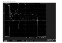
For those who would like to say, based on the previous shot, "who cares"...
Here it is the same setup, same shot, but with high (amplitude) resolution.
Again, normalized. (The shot with no att. was done with 20mV/div, the shot with att. inserted was done, as shown, with 6.9mV/div)
Important: the traces are swapped now,
Upper trace: attenuator inserted
Lower trace: no att.
Ciao, George
Attachments
Last edited:
Ok.
Here it is the difference before / after the insertion of an attenuator into a deliberately "wrongly" terminated 75ohm transmission line.
the setup is:
Upper trace
generator - 75ohm line - BNC tee (real 75ohm) - 75ohm termination.
The BNC tee goes into the 1Mohm input of my scope.
Lower trace
generator - 75ohm line - 10dB 75ohm attenuator-BNC tee - 75ohm termination
The BNC tee goes into the 1Mohm input of my scope
As you see, the only diffeence is the attenuator. The traces are normalized, so as to see the same percentage of the reflections.
I did not put up here the Hiface driver, because:
-I do not intend to discuss about it's output waveform
-I've put it on Diyhifi.org, please go and see.
The driver used is a 250MHz Hp pulse generator. The rise & fall times, ~700psec are limited by the scope.
The Hiface is only slightly worse, 1.8nsec rise time.
Last but maybe most important note: I show this setup & graphs again and again, because EXACTLY THIS IS the difference what your dac sees on it's input.
Ciao, George
Hmm, the rising and falling edges look excellent to me on both traces. I see no reason to believe that either one will perform any better with respect to jitter. The small amount of noise on the first trace is insignificant; it can not and will not affect the Hi/Lo transition in the receiver.
I hate linking to other forums, and I don't want to get dragged into this personally, but check this thread out from November:
DIYHiFi.org • View topic - SPDIF Cable Length
... Notice that barely 6 months ago, our original poster here was just getting to know a bit of practical transmission line advice. He didn't comprehend a lot of it, miscomprehended a bunch of it also. Now he's an expert, it seems - good to know we gave him a shove in the right direction.
But anyway, back to the subject... Don't bother with attenuators, unless you've got a situation that demands one, eg. keeping a source from overdriving the endpoint. You'll only get an improvement with an attenuator provided:
- The endpoint impedance is bad to start with.
- The quality of your attenuator is better than your endpoint.
- There's sufficient attenuation to make a significant impedance improvement.
- The voltage reduction from your attenuator doesn't cause issues with the receiver at the endpoint.
You're better off just improving the termination at the end. Unfortunately there's no real magic bullet for that other than measure and tweak.
Now, I know of a better "breakthrough" idea, alas I can't take credit for because (1) I never came up with the idea and (2) I'm not attempting to make myself DIY audio famous. Anyway, take the velocity factor of your cable into consideration, along with the SPDIF symbol rate at your typical rate (44.1/48/whatever) and pick a length such that when the first two reflections strike the end device, they're well outside of the transition window. You'll have just built yourself a cable that mitigates the effect of bad source/end termination! See linked thread above for more info.
Last edited:
You are referring to me - I don't think this has anything to do with the thread, why post it?I hate linking to other forums, and I don't want to get dragged into this personally, but check this thread out from November:
DIYHiFi.org • View topic - SPDIF Cable Length
... Notice that barely 6 months ago, our original poster here was just getting to know a bit of practical transmission line advice. He didn't comprehend a lot of it, miscomprehended a bunch of it also. Now he's an expert, it seems - good to know we gave him a shove in the right direction.
I'm no expert & never have pretended to be then or now (I hope you're not being facetious here?) - I'm just a learner with an inquisitive mind who asks questions. If this upsets or annoys anyone, I'm sorry, it's in the nature of learning. Without wanting to start another spat, I comprehended more than I was/am given credit for then & now so again if this is some put-down, I don't know why you are posting it here?
Anyway, as I said then & again now, thank you for your posts on that linked to thread, they were this learners beacon in that stormy sea.
Again, thank you for a well conceived post!But anyway, back to the subject... Don't bother with attenuators, unless you've got a situation that demands one, eg. keeping a source from overdriving the endpoint. You'll only get an improvement with an attenuator provided:
- The endpoint impedance is bad to start with.
- The quality of your attenuator is better than your endpoint.
- There's sufficient attenuation to make a significant impedance improvement.
- The voltage reduction from your attenuator doesn't cause issues with the receiver at the endpoint.
You're better off just improving the termination at the end. Unfortunately there's no real magic bullet for that other than measure and tweak.
Can I ask something here Gmarsh which I would have asked on that thread you linked to if it hadn't been closed down - Again, not wishing to be fractious, just trying to learn:Now, I know of a better "breakthrough" idea, alas I can't take credit for because (1) I never came up with the idea and (2) I'm not attempting to make myself DIY audio famous. Anyway, take the velocity factor of your cable into consideration, along with the SPDIF symbol rate at your typical rate (44.1/48/whatever) and pick a length such that when the first two reflections strike the end device, they're well outside of the transition window. You'll have just built yourself a cable that mitigates the effect of bad source/end termination! See linked thread above for more info.
Is there also a length below which the cable will not show "transmission line" behaviour?
The TL effects come from the delayed return of energy. If the delay in the cable is so short that the returned energy is returned much faster than the signal rises, then we may reasonable conclude that no transmission line effects occur.
As many common cmos outputs have a risetime of around 10 - 20nS can we actually get away okay with a cable of around 30cm length as having no significant TL effects?
Can I also ask in relation to long cables:
- as you lengthen the cable there will be certain lengths where the reflections fall outside the rise-time window BUT lengthen it further & this reflection could well now hit the next rise-time window - so there are only discrete lengths that will work which have to be calculated?
Also this length will change depending on the datarate so it will be different for 44.1, 88,2, 96,176, 192KHz speeds, no? Does this mean we have to have different length cables for different speeds? Swapping cables when listening to music at different rates would not be fun!
PS. - I see how quiet it has become around here after Joseph K posts - I hope this is because some people are actually reviewing their original opinions & opening up to new information!
Last edited:
[snip]PS. - I see how quiet it has become around here after Joseph K posts - I hope this is because some people are actually reviewing their original opinions & opening up to new information!
Well Joseph K's post certainly made me think! As I also said, I had some pretty convincing emails from Jocko (but I don't want to become his messenger here). So I do think there is something to this atten stuff.
But Gmarsh summed it up nicely: there a lot of factors invoved that can make matters even worse. What hasn't been addressed: how are you going to splice that atten in? Soldering? BNC connectors and an extra cable? Might make things worse in the end.
Intuitively I like solution that take away the root cause: better cables, better termination, possible trying to get a cable that is too short for the effect to have, ehhh, effect. We all know that transmission line effects in speaker cables don't exist because speaker cables are too short for the wavelengths involved. With a freq of 6MHz for S/PDIF (I think) and a wave propagation of 0.8c in a cable, the wavelength is around 160ft if I'm not mistaken. That already makes most cables electrically short. Did I get my numbers right?
jd
Yes he did a nice job in summarising it.Well Joseph K's post certainly made me think! As I also said, I had some pretty convincing emails from Jocko (but I don't want to become his messenger here). So I do think there is something to this atten stuff.
But Gmarsh summed it up nicely: there a lot of factors invoved that can make matters even worse.
These attenuators come in a high quality BNC plug which is just put on the end of the cable (at whichever end or both that you want)What hasn't been addressed: how are you going to splice that atten in? Soldering? BNC connectors and an extra cable? Might make things worse in the end.
Don't know about your numbers, I'm not good n that area!Intuitively I like solution that take away the root cause: better cables, better termination, possible trying to get a cable that is too short for the effect to have, ehhh, effect. We all know that transmission line effects in speaker cables don't exist because speaker cables are too short for the wavelengths involved. With a freq of 6MHz for S/PDIF (I think) and a wave propagation of 0.8c in a cable, the wavelength is around 160ft if I'm not mistaken. That already makes most cables electrically short. Did I get my numbers right?
jd
I agree about addressing root causes as a first action but I started this whole thread to introduce the idea for experimenting with in certain circumstances & NOT as a solution to all ills in digital audio
I was/am hoping that some might do the experiment & report their results - that's what this forum is about, isn't it?
For those requiring a little more reading material - here's one about SPDIF cable length, reflections & impedance matching spdif
Nice article, can't shoot any holes in his reasoning. And I guess Steve is one of those qualified people who CAN do this mod
The only thing left is how the increase in jitter will impact the sound. Again this points to a good DAC with independent clocking. When you have that, jitter at the receiver becomes irrelevant as long as you don't miss any bits. That means that audible differences from the transmission jitter can be completely avoided.
jd
Is there also a length below which the cable will not show "transmission line" behaviour?
The TL effects come from the delayed return of energy. If the delay in the cable is so short that the returned energy is returned much faster than the signal rises, then we may reasonable conclude that no transmission line effects occur.
In order for transmission line behaviour to be considered to be definitely absent, a length of one quarter of a wavelength or less is generally taken, although some authors prefer to take a value of one tenth. Taking into account the velocity factor of the medium.
If you google 'electrically short transmission line' you will find numerous references.
Deciding on the wavelength is a moot point in this case though, as the pulses are not sinusoidal, but square(ish), and in order to maintain the integrity of the shape, a minimum of the 11th harmonic is probably required for a reasonable approximation.
PS. - I see how quiet it has become around here after Joseph K posts - I hope this is because some people are actually reviewing their original opinions & opening up to new information!
No, I thought macboy dealt with this quite adequately, and I was hoping the whole thing had died.
w
Oh, that guy Steve, he's a salesman.
Last edited:
See the section in Electromagnetic compatibility handbook - Kenneth L. Kaiser
Electromagnetic compatibility handbook - Google Books
13.21 Receiver Voltage when Rise Time >> Line Delay
'...line terminations for matching purposes are recommended when the one-way delay is equal to or greater than one-sixth of the rise time.'
w
Electromagnetic compatibility handbook - Google Books
13.21 Receiver Voltage when Rise Time >> Line Delay
'...line terminations for matching purposes are recommended when the one-way delay is equal to or greater than one-sixth of the rise time.'
w
I was playing with radios some time ago, and I remember that the cable of the antennas had to have a length that was a multiple of of 11 meters for 27 MHz.
I don't know if this is relevant for spdif transmission.
D.
This is not correct at all.
_-_-bear
See the section in Electromagnetic compatibility handbook - Kenneth L. Kaiser
<snip>
13.21 Receiver Voltage when Rise Time >> Line Delay
'...line terminations for matching purposes are recommended when the one-way delay is equal to or greater than one-sixth of the rise time.'
w
There *is* a line termination on all SPDIF inputs.
_-_-
- Status
- Not open for further replies.
- Home
- Source & Line
- Digital Source
- RF Attenuators = Jitter Reducers