Nice work Valery.
There is also another small and nice old school trick.
Try to simulate double bootstrap on the predrivers, it works reallly well.
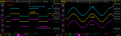
There is way less thermal losses at the predriver stage so it is easier to get it compensated. Transistors are working with ''constant'' VCE, linearity is improoved, most of the Cob disapears (bootstraped collector voltage), and most important it works well. In my example bellow the main PSU voltage is 2 x 58Vdc and the predrivers are getting only 28V instead.
My soundcard is not good enough to measure OPS properly, but is good enough to check if there is some problems with it. Worth of trying anyway.
Regards
Peter
Some files bellow + youtube movie in forein language
https://youtu.be/WAOLeGbGXwM
There is also another small and nice old school trick.
Try to simulate double bootstrap on the predrivers, it works reallly well.
There is way less thermal losses at the predriver stage so it is easier to get it compensated. Transistors are working with ''constant'' VCE, linearity is improoved, most of the Cob disapears (bootstraped collector voltage), and most important it works well. In my example bellow the main PSU voltage is 2 x 58Vdc and the predrivers are getting only 28V instead.
My soundcard is not good enough to measure OPS properly, but is good enough to check if there is some problems with it. Worth of trying anyway.
Regards
Peter
Some files bellow + youtube movie in forein language
https://youtu.be/WAOLeGbGXwM
Attachments
Last edited:
Thanks.
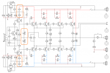
Please look again, in the schematic above the bootstrap is only providing constant VCE for the predrivers only. The output swing remain the same in this case.
I remember when I have used bootstrap for the whole IPS than the THD at the higher amplitudes was a bit higher in every case.
Here the THD is better in every case, this is the trick.
\
Regards
Nice work Valery.
There is also another small and nice old school trick.
Try to simulate double bootstrap on the predrivers, it works reallly well.
There is way less thermal losses at the predriver stage so it is easier to get it compensated. Transistors are working with ''constant'' VCE, linearity is improoved, most of the Cob disapears (bootstraped collector voltage), and most important it works well. In my example bellow the main PSU voltage is 2 x 58Vdc and the predrivers are getting only 28V instead.
My soundcard is not good enough to measure OPS properly, but is good enough to check if there is some problems with it. Worth of trying anyway.
Regards
Peter
Some files bellow + youtube movie in forein language
https://youtu.be/WAOLeGbGXwM
Why C28, C29 (330u I think, not very well visible) used here? Don't thy eat all bootstrap voltage?
Damir, those are 330pF - compensation.
Valery, I don't think it can compensate anything in this position.
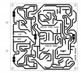
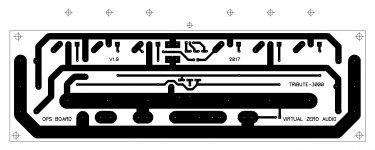
TRIBUTE-3000 - Driver board layout for etching
Just finished the driver board layout. Etching-friendly, 4.75 x 4.75 inch, single layer, only 3 jumper wires on the top side.
Output board is in the process now- hope to publish it soon.
Cheers,
Valery
Just finished the driver board layout. Etching-friendly, 4.75 x 4.75 inch, single layer, only 3 jumper wires on the top side.
Output board is in the process now- hope to publish it soon.
Cheers,
Valery
Attachments
-
13-Tribute-3000-01-Etching-Bottom.pdf42 KB · Views: 160
-
12-Tribute-3000-01-Etching-Bottom-Mirrored.pdf42.1 KB · Views: 143
-
11-Tribute-3000-01-Etching-Silk-Mirrored.pdf72 KB · Views: 130
-
10-Tribute-3000-01-Etching-Silk.pdf72.2 KB · Views: 165
-
 09-Tribute-3000-Bottom.JPG135.8 KB · Views: 1,057
 -
 08-Tribute-3000-Silk.JPG149.8 KB · Views: 1,071
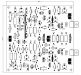
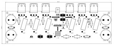
TRIBUTE-3000 - OPS board layout for etching
Here goes my version of the output board - also etching-friendly, single-layer, with 2 jumper wires.
The idea is that this board is attached to the heatsink - either vertically, or horizontally, being connected to the horizontally-placed driver board with 2 flat cables, 3 (or 6) wires each.
Cheers,
Valery
Attachments
-
23-Tribute-3000-01-OPS-Etching-Bottom.pdf21.9 KB · Views: 132
-
22-Tribute-3000-01-OPS-Etching-Bottom-Mirrored.pdf21.8 KB · Views: 105
-
21-Tribute-3000-01-OPS-Etching-Silk-Mirrored.pdf35 KB · Views: 176
-
20-Tribute-3000-01-OPS-Etching-Silk.pdf35.1 KB · Views: 144
-
 19-Tribute-3000-Bottom.JPG96.4 KB · Views: 979
 -
 18-Tribute-3000-OPS-Silk.JPG124.7 KB · Views: 1,024
Those small capacitors 330pF they are ''killing'' bootstrap for the very high frequency (creating short path to GND), it is for the safety reasons.
Regards
Hi Peter,
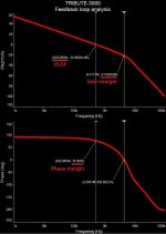
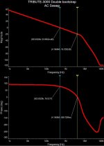
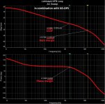
I've noticed an interesting effect with the double-bootstrap at pre-drivers in this design - see the feedback loop analysis curves. The double-bootstrapped magnitude curve goes steeper after the pole at around 6MHz, so that the following zero is moved to lower frequencies (some 60MHz). I can't explain this effect so far - so I have left my initial configuration in place, until I get more understanding of what's going on.
My simulation also does not show any distortion reduction - performance is practically the same. I will run some more experiments though.
Cheers,
Valery
Attachments
Hi Valery... see the feedback loop analysis curves...
How do you do loop analysis in your simulator?
Simple loop probes can be inaccurate for circuits that have non trivial feed-thru or other non-ideal behavior.
Perhaps that is what you have here.
LTSpice has a nice Tian probe but even that is not totally accurate.
Best wishes
David
Hi Valery
How do you do loop analysis in your simulator?
Simple loop probes can be inaccurate for circuits that have non trivial feed-thru or other non-ideal behavior.
Perhaps that is what you have here.
LTSpice has a nice Tian probe but even that is not totally accurate.
Best wishes
David
Hi David,
Missed your post here somehow.
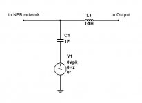
I'm using a "simplified" method, injecting AC signal into the feedback loop, as shown on the picture, then just building a Bode plot accordingly.
In most cases the results are rather accurate (I did some comparisons with Tian probe analysis for some similar circuits in the past).
Although, I agree - in some "difficult" setups there may be some discrepancies.
Cheers,
Valery
Attachments
Lichtstark - very accurate, fast, rather simple front-end
Hello All,
I think, I've reached the "Nirvāna"
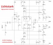
Exploring the ways of using the current-driven VAS topology the best possible way, I first came to some rather complicated setups, then, simplifying things down, I came to what you see attached.
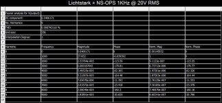
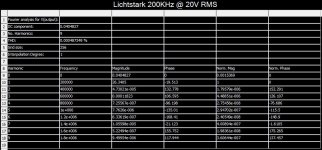
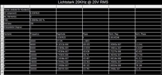
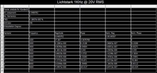
Dual LTP (trans-conductance stage), directly driving two enhanced cascoded high-precision current mirrors (current scaling + trans-impedance stage). That's it. Short signal path and lots of accuracy. You can see the levels of THD (from 0.00006% at 1KHz to 0.0005% at 200KHz). It's not a typo - it's bloody 200KHz.
Also - around 250V/uS slew rate when used standalone (despite the fact it's a VFA discrete op-amp in fact).
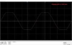
In combination with NS OPS, running the 8 ohm load at 20V RMS (50W RMS power level), it's still showing some 0.00075% THD at 1 KHz.
Nice clean clipping, unconditional stability with very light compensation (see stability margins in combination with NS-OPS, picture 2).
It would be also interesting to test this one with the Ostripper's latest OPS ( the Arc Welder monster board).
For using with the lower rails, some resistor values need to be adjusted.
The VAS idle current is around 5.75mA.
Let me know if there will be some questions.
Cheers,
Valery
P.S. By the way - setup, offered by Paul here, using my VAS topology, is also very cool. The right way of thinking
Hello All,
I think, I've reached the "Nirvāna"
Exploring the ways of using the current-driven VAS topology the best possible way, I first came to some rather complicated setups, then, simplifying things down, I came to what you see attached.
Dual LTP (trans-conductance stage), directly driving two enhanced cascoded high-precision current mirrors (current scaling + trans-impedance stage). That's it. Short signal path and lots of accuracy. You can see the levels of THD (from 0.00006% at 1KHz to 0.0005% at 200KHz). It's not a typo - it's bloody 200KHz.
Also - around 250V/uS slew rate when used standalone (despite the fact it's a VFA discrete op-amp in fact).
In combination with NS OPS, running the 8 ohm load at 20V RMS (50W RMS power level), it's still showing some 0.00075% THD at 1 KHz.
Nice clean clipping, unconditional stability with very light compensation (see stability margins in combination with NS-OPS, picture 2).
It would be also interesting to test this one with the Ostripper's latest OPS ( the Arc Welder monster board).
For using with the lower rails, some resistor values need to be adjusted.
The VAS idle current is around 5.75mA.
Let me know if there will be some questions.
Cheers,
Valery
P.S. By the way - setup, offered by Paul here, using my VAS topology, is also very cool. The right way of thinking
Attachments
-
 Lichtstark-Scope_Clipping.JPG159.1 KB · Views: 106
 -
 Lichtstark-NS_THD_001K.JPG91.4 KB · Views: 94
 -
 Lichtstark_THD_200K.JPG90 KB · Views: 85
 -
 Lichtstark_THD_020K.JPG91.1 KB · Views: 120
 -
 Lichtstark_THD_001K.JPG90.5 KB · Views: 163
 -
 Lichtstark_NFB_Loop_AC.JPG346.5 KB · Views: 486
 -
 Lichtstark_Front_Sch.JPG168.1 KB · Views: 490
 -
 Lichtstark-Square-200KHz.JPG149.9 KB · Views: 141
- Home
- Amplifiers
- Solid State
- Revisiting some "old" ideas from 1970's - IPS, OPS