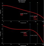
Terry, can you please try this variant. The simplest and the cleanest one. Simulated AC analysis looks great. I still keep it rather fast. I there will be still some oscillation, we will just slow it down significantly with higher cap values next time.
So, we remove all the small caps, leaving in place only C9, C11 and C13 (see the values).
We also amend R5 and R8. Now, if you will not be able to zero-out the offset, just slightly change R8 (one step, like from 220 to 240). Higher value will move the offset in negative direction. And then just fine-tune with the trimmer.
R23 - for TubSuMo = 47, for Slew = 130.
It's coming")
So, we remove all the small caps, leaving in place only C9, C11 and C13 (see the values).
We also amend R5 and R8. Now, if you will not be able to zero-out the offset, just slightly change R8 (one step, like from 220 to 240). Higher value will move the offset in negative direction. And then just fine-tune with the trimmer.
R23 - for TubSuMo = 47, for Slew = 130.
It's coming
Attachments
OK it looks like you also left in C6 so I did too. It is better. The oscillation with the input shorted is gone. It still oscillates some with the load attached but is better. Pics attached.
One thing of note. It oscillates at all frequencies with a square wave, but with a sine wave I can see oscillation at 1khz but not at 10khz. The oscillation begins at about 6vac output. No oscillation visible without a load attached.
One thing of note. It oscillates at all frequencies with a square wave, but with a sine wave I can see oscillation at 1khz but not at 10khz. The oscillation begins at about 6vac output. No oscillation visible without a load attached.
Attachments
OK it looks like you also left in C6 so I did too. It is better. The oscillation with the input shorted is gone. It still oscillates some with the load attached but is better. Pics attached.
One thing of note. It oscillates at all frequencies with a square wave, but with a sine wave I can see oscillation at 1khz but not at 10khz. The oscillation begins at about 6vac output. No oscillation visible without a load attached.
Many thanks Terry! C6 - you're right, should be there. I'll check a couple of other things and come back.
Silly me, I read them as shadows.............It it 0.1uS setting? The value between the black marks?
Then it oscillates at around 2.85MHz...
Even more "purity"
Hi Terry,
Looks like too much gain in the VAS became a problem. So, I decided to go away from the Darlington pair there. The topology becomes even simpler.
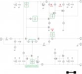
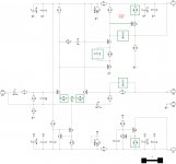
Could you please try this one. Green boxes indicate the parts/values changed.
R18 and Q9 are removed, Q9's b-e is jumpered so that Q11's base goes to Q7's collector.
R22 = R23 = 100 makes it suitable for both Slewmaster and Tubsumo at 7mA VAS current.
Cheers,
Valery
Hi Terry,
Looks like too much gain in the VAS became a problem. So, I decided to go away from the Darlington pair there. The topology becomes even simpler.
Could you please try this one. Green boxes indicate the parts/values changed.
R18 and Q9 are removed, Q9's b-e is jumpered so that Q11's base goes to Q7's collector.
R22 = R23 = 100 makes it suitable for both Slewmaster and Tubsumo at 7mA VAS current.
Cheers,
Valery
Hi Valery,
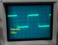
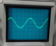
That seems to have done the trick. No more issues with a load attached. I am attaching some scope shots. This has really good bass response. This is tested with the Slew mini latet OPS.
R8=220r gives about 0 offset with the trimmer full throw. The next step I had was 270r with was too much so I had to parallel a 2k2 then I was able to zero the offset. I had 180r in there due to modification in post #92.
Blessings, Terry
Attachments
-
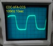 CDC CFA CCS 100khz.jpg49.8 KB · Views: 125
 -
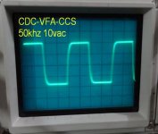 CDC CFA CCS 50khz.jpg47.3 KB · Views: 116
 -
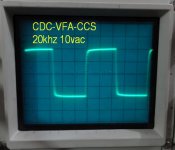 CDC CFA CCS 20khz.jpg47.8 KB · Views: 118
 -
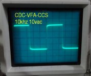 CDC CFA CCS 10khz.jpg45.2 KB · Views: 108
 -
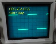 CDC CFA CCS 1khz.jpg44.4 KB · Views: 110
 -
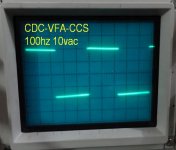 CDC CFA CCS 100hz.jpg48.1 KB · Views: 110
 -
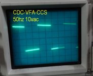 CDC CFA CCS 50hz.jpg48.3 KB · Views: 114
 -
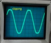 CDC CFA CCS clipping.jpg46.5 KB · Views: 498
Bingo!
Terry - thanks a lot! Now it looks really good. It may be fine-tuned for even sharper sq wave response, but even now it looks good.
This is one of the options for CFA-fast VFA. Complementary Differential Circuit really does its job.
I'm very happy with the result now, which could not be achieved without your help for sure
We will correct the layouts for other builders.
Cheers,
Valery
Hi Valery,
That seems to have done the trick. No more issues with a load attached. I am attaching some scope shots. This has really good bass response. This is tested with the Slew mini latet OPS.
R8=220r gives about 0 offset with the trimmer full throw. The next step I had was 270r with was too much so I had to parallel a 2k2 then I was able to zero the offset. I had 180r in there due to modification in post #92.
Blessings, Terry
Terry - thanks a lot! Now it looks really good. It may be fine-tuned for even sharper sq wave response, but even now it looks good.
This is one of the options for CFA-fast VFA. Complementary Differential Circuit really does its job.
I'm very happy with the result now, which could not be achieved without your help for sure
We will correct the layouts for other builders.
Cheers,
Valery
Gentlemen,
I am impressed! That looks to be a simple yet effective circuit. I have a fascination for simple elegance.
Valery will you be posting a final, final schematic soon? What will you be naming this new IPS?
Hi Carl,
Thank you for the feedback
Yes, this is a pretty cool one. Even I like it (which is not always the case
).I did not come up with some real name yet - I will - so for now the temporary name is CDC-VFA-CCS
Complementary differential - 2-nd stage - provides speed and linearity at the same time. Also, a great advantage - it's a great link between the low-railed LTP and high-railed VAS, so it's easy to build some high-swing (read - high power) designs.
I will drop the final schematic together with updated PCB here soon
Cheers,
Valery
Hi Valery,
What I have right now is the schematic from post #102 with the changes you described in post #106. So R6 and R9 are still 110R, C13 is 22p, C11 is 4p7 and no C5. If you think it will help I will make those changes too though I doubt I have a 2p2 cap.
Hi Terry, actually, it would be interesting to test. Then, let's leave R6, R9 = 110R, C13 (in Post#111 it's C12 - sorry for that) = 22p, as they are now. You can get close to 2.2p, using 2 x 4.7p in series. All the rest - as shown in Post #111. It should zero-out with R8=220R, but if not - you handle it perfectly.
This way, it's going to be a little bit "sharper" on the edges.
Thank you,
Valery
Wow, I should have noticed that you changed the number on the schematic from C12 to C13. C12 is the correct label I just checked it against the PCB. What's strange is that it is working so well with C12 pulled and C13 installed. Tomorrow I will make all the latest changes and test again.
Fun Stuff
Fun Stuff
Hi Terry,
In fact, the variant you've got now (with C13 installed) is excellent - I've checked it in a number of simulations.
Can you please try C11, say, 1pf - if you've got the value that small - leaving all the rest just as is?
If it runs well, you can try to reduce C13 from 22p to 15p. This is going to give the sharpest corners.
Then we select the best option for compensation caps.
As a final touch, you can change the resistors for the best balance of the circuit:
R22 = R23 = 100
R8 = 220
Then we can publish the final schematic, correct the PCBs, etc.
Cheers,
Valery
Are these changes going to go into cdc-vfa-symm before it's tested?
Yep. As soon as we finalize this fine-tuning, I will update the symmetric one accordingly
Yep. As soon as we finalize this fine-tuning, I will update the symmetric one accordingly
It'll be nice to loose a few parts in that one.
- Home
- Amplifiers
- Solid State
- Revisiting some "old" ideas from 1970's - IPS, OPS