Yes, right - 0.1 uF is just a reasonable combination of the size and capacitance, so 0.22 uF is no problem - even better.
Terry, as usual, I would recommend to test the boards standalone first - you can connect PD+, ND- and NFB together and the whole thing will work as a 29db gain stage. You can measure the resulting VAS standing current, measuring the voltage over CCS's emitter resistor and then calculating.
Terry, as usual, I would recommend to test the boards standalone first - you can connect PD+, ND- and NFB together and the whole thing will work as a 29db gain stage. You can measure the resulting VAS standing current, measuring the voltage over CCS's emitter resistor and then calculating.
Yes, right - 0.1 uF is just a reasonable combination of the size and capacitance, so 0.22 uF is no problem - even better.
Terry, as usual, I would recommend to test the boards standalone first - you can connect PD+, ND- and NFB together and the whole thing will work as a 29db gain stage. You can measure the resulting VAS standing current, measuring the voltage over CCS's emitter resistor and then calculating.
Forgive my ignorance again. which is the CCS emitter resistor?
Thanks, Terry
Forgive my ignorance again. which is the CCS emitter resistor?
Thanks, Terry
Ah, on the schematic from Post #48, it's R23 (130R). If everything goes right, you will have some 0.7V over R23. Dividing it by 130R will give you around 5.5mA of VAS current.
You can do the same thing with R22 (VAS degeneration resistor), ending up with the same current value.
Connections and gain.
Okay, now for a really dumb question...what does "PD+ and "ND-" stand for?
I see those connections on a lot of IPSs, mostly from ostripper.
Also, to use any of these IPSs as a line stage, all you need to do is tie the PD+, ND- and negative feedback connections together and place a volume pot in front of it?
Gain at 29dB sounds quite high for a line stage, especially with sources that output about 2V.
What changes would have to be made to this circuit to lower the gain, or would that make the circuit unstable?
Thanks...
Terry, as usual, I would recommend to test the boards standalone first - you can connect PD+, ND- and NFB together and the whole thing will work as a 29db gain stage. You can measure the resulting VAS standing current, measuring the voltage over CCS's emitter resistor and then calculating.
Okay, now for a really dumb question...what does "PD+ and "ND-" stand for?
I see those connections on a lot of IPSs, mostly from ostripper.
Also, to use any of these IPSs as a line stage, all you need to do is tie the PD+, ND- and negative feedback connections together and place a volume pot in front of it?
Gain at 29dB sounds quite high for a line stage, especially with sources that output about 2V.
What changes would have to be made to this circuit to lower the gain, or would that make the circuit unstable?
Thanks...
Hi, PD+ and ND- are the positive and negative output terminals of the front-end section.
Yes, to use it as a line stage - just tie those terminals together and connect NFB to that point.
29db is a de-facto standard voltage gain for the power amp (good to have it standardized in case you want to exchange the power amp in your system).
Of course, for a pre-amp line stage you need to decrease it. The gain is purely set by NFB resistors - R16, R17 on the schematic in Post #48.
Gain (as a number of times): G = R17/R16 +1
Gain in db: Gdb = 20 log (G)
For decreasing the gain, increase R16 appropriately. For gain = 2 (6db), R16 = R17 = 27K
Cheers,
Valery
Valery, thank you for your very helpful and informative reply!
I hope to get a pair(or more) of the through-hole boards for this design when Jeff gets the gerbers for them.
I'll also be looking forward to still's opinions on the sound quality vs. some of the other IPSs he's already built.
I hope to get a pair(or more) of the through-hole boards for this design when Jeff gets the gerbers for them.
I'll also be looking forward to still's opinions on the sound quality vs. some of the other IPSs he's already built.
Hi Terry,10uF bipolar.
I did not want to make fun of you. But the space provided for C1 was obviously planned for a film capacitor.
Only, it's looks funny
")
Personally, I also believe that a large electrolytic capacitor is sufficient as a coupling capacitor.
Regards
Patrick
Lol, yes I know Jeff allowed for many sizes of caps. I have a lot of parts on hand but not every part. If for some reason this IPS turns out to find its way into a completed amplifier I might change it. To date I have not heard a difference between using a fancy cap in that position despite popular opinion. In fact, I may just short that cap during testing. I build too many amps to be buying a lot of expensive blocking caps when they likely won't affect the results of the test.
Blessings, Terry
Blessings, Terry
Through-Hole PCB.
Jeff, are you going to do a through-hole version of the SYMM as well?
Thanks...
I've got CDC-VFA-SYMM layed out. There's room to change D1 and D6 to SMT devices in needed.
Jeff, are you going to do a through-hole version of the SYMM as well?
Thanks...
Jeff, are you going to do a through-hole version of the SYMM as well?
Thanks...
Yes I am. I've gotten a little overloaded wiyh work, but should have it done soon.
OK I have it playing. Sounds fine but it clips funny and has some "stuff" on the square wave. One note is that I didn't have a couple of the exact values for the small caps. C11 is a 6.8p and a 2p in series, (measures 4.8p on my meter) and C13 is a 5.8p. All others are what is called for. I am using my Mini Slew OPS 1P latfet. Scope shots taken at 7.5khz
Attachments
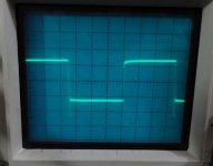
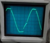
OK I have it playing. Sounds fine but it clips funny and has some "stuff" on the square wave. One note is that I didn't have a couple of the exact values for the small caps. C11 is a 6.8p and a 2p in series, (measures 4.8p on my meter) and C13 is a 5.8p. All others are what is called for. I am using my Mini Slew OPS 1P latfet. Scope shots taken at 7.5khz
Terry, thanks a lot for the info - I will analyze it. Probably, I need to "slow it down" a bit.
Hi Terry, please remove C15, R20. You can also optionally increase C13 up to 22pF.
Spikes at the bottom should be gone. Referring to schematic from Post #48.
It is also recommended that there are no shunt capacitors at the input of the OPS (sitting between b-c of the pre-drivers in some OPS modules).
Cheers,
Valery
Spikes at the bottom should be gone. Referring to schematic from Post #48.
It is also recommended that there are no shunt capacitors at the input of the OPS (sitting between b-c of the pre-drivers in some OPS modules).
Cheers,
Valery
caps in series:OK I have it playing. Sounds fine but it clips funny and has some "stuff" on the square wave. One note is that I didn't have a couple of the exact values for the small caps. C11 is a 6.8p and a 2p in series, (measures 4.8p on my meter) and C13 is a 5.8p. All others are what is called for. I am using my Mini Slew OPS 1P latfet. Scope shots taken at 7.5khz
add up using the same parallel resistor formula.
1/C = 1/C1 + 1/C2 for two in series.
This simplifies to C = C1*C2 / {C1+C2}
6p8F and 2pF = 1p54F +- an enormous tolerance, (the 2pF could be +-20%)
Is the first sqw the test signal, or the output signal?
It helps interpret the signals if both test and output are displayed on the same screen.
I've managed to get a through hole version of CDC-VFA-SYMM layed out but I had to enlarge the board and add 14 jumper wires to get it connected . There's a lot of components to this input but as layed out will fit quite nicely on a 3" x 4" standard double sided Slewmaster input board.
. There's a lot of components to this input but as layed out will fit quite nicely on a 3" x 4" standard double sided Slewmaster input board.Attachments
Last edited:
Hi Terry, please remove C15, R20. You can also optionally increase C13 up to 22pF.
Spikes at the bottom should be gone. Referring to schematic from Post #48.
It is also recommended that there are no shunt capacitors at the input of the OPS (sitting between b-c of the pre-drivers in some OPS modules).
Cheers,
Valery
Hi Valery,
I will try a couple different OPS before I make changes. I should have done that first I suppose. Just being lazy.
AndrewT,
I didn't do the math. I measured them with my meter. That combination got me the closest. I mentioned it for Valery's benefit to help in evaluation, not suggesting it as good practice. Shots are the output.
I realise that you measured. The numbers indicated a DMM offset issue at very low capacitance values.
Nothing wrong with using two very small caps in series to give a lower value cap.
Two 10pF +-1pF in series gives 5pF +-1pF for the combination. 4pF to 6pF
Whereas a 4p7F +-1pF is effectively a different capacitor over a small part of the range. 3p7F to 5pF7
And you have the opportunity to measure the two 10p in parallel, you get 20pF+-2pF +-DMM tolerance to let you home in on that ~5pF more accurately.
Using ~1p5F may be why the ripples are seen on the sqw test.
BTW,
if you need 5pF and have 6p8F then adding either 15pF, or 18pF, or 22pF, gets you close.
Last edited:
Hi Valery,
I haven't tried any modifications yet. I wanted to report on some findings trying other OPS first. The Tubsumo OPS looks better. I still see the slight overshoot on the square waves but they are top and bottom equally. However, I still see latching on clip. The Slewmaster 5P OPS will not work at all. Big surging on my light bulb tester and it will not come up on power.. With the big slew OPS I'm seeing 3.4V on PD+ and 100mV on ND- but as I said is surging badly and pulling way too much current.
With the Tubsumo OPS attached, I read .633V across R23 so about 4.8mA for the VAS. Next I will try lifting a leg on R20 an see what that does to the overshoot and latching.
Right now the Slewmaster OPS is a no-go.
Blessings, Terry
EDIT: I reattached the Tubsumo OPS and retested at 7.5khz and I actually see exactly the same thing as with the little Mini OPS. I then lifted R20 and there is no change at all. I will try raising C13 to 22p and see if that helps.
Last edited:
Hi Valery,
Did some more testing. 22p in C13 made the square wave sides sloped, especially the leading leg. Top of the wave is flat but the bottom still has the overshoot. Clipping looks as bad as before. R20 in or out makes no difference. Adding an 8ohm load causes the bias to shoot up. Actually blew fuses first time I tried it so I went back to using the light bulb. It acts like there is too much gain?
Did some more testing. 22p in C13 made the square wave sides sloped, especially the leading leg. Top of the wave is flat but the bottom still has the overshoot. Clipping looks as bad as before. R20 in or out makes no difference. Adding an 8ohm load causes the bias to shoot up. Actually blew fuses first time I tried it so I went back to using the light bulb. It acts like there is too much gain?
- Home
- Amplifiers
- Solid State
- Revisiting some "old" ideas from 1970's - IPS, OPS