millerlitescott said:Would you pick up the sub output signal off of where you would connect the input signal to the PCB board and run it to a sub out RCA?
Yep. Its that simple.
Hey Matt,
Loving the look of your amp. Especially the big chunky volume control.
How did you make the cover for the Power Transformer?
I was thinkinng of doing something similar but wasn't sure if I could take the Transformer apart without damaging it. I don't know what yours was like but mine is covered in thread lock/glue.
As the input power leads point down and the output points up its a bit of a pain trying to get the leads through the chassis.
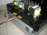
For the Output Transformers I took the case apart and turned them upside-down.
Loving the look of your amp. Especially the big chunky volume control.
How did you make the cover for the Power Transformer?
I was thinkinng of doing something similar but wasn't sure if I could take the Transformer apart without damaging it. I don't know what yours was like but mine is covered in thread lock/glue.
As the input power leads point down and the output points up its a bit of a pain trying to get the leads through the chassis.
For the Output Transformers I took the case apart and turned them upside-down.
Ben10 said:Hey Matt,
Loving the look of your amp. Especially the big chunky volume control.
How did you make the cover for the Power Transformer?
I was thinkinng of doing something similar but wasn't sure if I could take the Transformer apart without damaging it. I don't know what yours was like but mine is covered in thread lock/glue.
As the input power leads point down and the output points up its a bit of a pain trying to get the leads through the chassis.
For the Output Transformers I took the case apart and turned them upside-down.
For the covers I started with some automotive steel (18 or 20 gauge, I can't remember they were just some scrap bits I found) and punched holes in the one side, used some math to calculate how much metal I would need between there and the other set of holes. Then I cut the metal to the height I wanted and punched the opposite side's holes. I bent the ends with the holes to a 90 degree angle. Then I took the 2" aluminum rod piece I made the knobs from and hand-bent the steel over it. After I had a nice semicircle I just took the long screws out of the transformer and put the plate on. For the other side a round plate wouldn't work so I had to bend it and beat it with a hammer a bit and squeeze it with a vice until it was the right shape. I replaced the bolts from the transformer with basically identical ones and bolted it together. I taped off the tops and the wires and painted the whole thing.
Matt,
Nice work!!
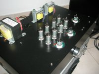
How did you get the transformers to sit where they are. I mean, are not the transformer wires really short to put them in that configuration? Did you extend the wires? If so how did you extend them? Are you hearing any noise from keeping them in that position?
Also I see that you are using a 3 pin power cord, where did you connect the third pin(ground) on the circuit?
Thanks.
Nice work!!
How did you get the transformers to sit where they are. I mean, are not the transformer wires really short to put them in that configuration? Did you extend the wires? If so how did you extend them? Are you hearing any noise from keeping them in that position?
Also I see that you are using a 3 pin power cord, where did you connect the third pin(ground) on the circuit?
Thanks.
stl said:Matt,
Nice work!!
How did you get the transformers to sit where they are. I mean, are not the transformer wires really short to put them in that configuration? Did you extend the wires? If so how did you extend them? Are you hearing any noise from keeping them in that position?
Also I see that you are using a 3 pin power cord, where did you connect the third pin(ground) on the circuit?
Thanks.
I extended all transformer wires except for the two output transformers Green and Black wires. They were just long enough to reach my board with the required slack. The rest I soldered high gauge wire to and heatshrunk to fill the distance. I have noticed much less noise than when using the supplied wooden plank, I think it may have to do with my EMI filtered power connector or the transformer frames being grounded by the chassis.
That being said, I connected the ground wire from the 3 pin to the chassis on the inside of the case. The EMI filter housing on the power plug grounds it to the chassis anyway but I figured I should connect the wire just to be safe.
Thanks Matt.
What software did you do the design in? It looks good.
I just got the kit and will start assembling it soon.
Here are the mods I am thinking of doing right away.
1> Replace the .22 mF caps with Sonicaps of the same kind.
2> Replace the 220, 100, 22 mF with 220, 220, 100mF Ruby caps.
Mods I want to do later but don't know how to (If you do please tell me how to):
1> Bleeder resistors.
2> Diode rectifier upgrade.
3> Ultra Linear Output transformer.
Thanks.
Frank
The only thing I can help you with is the diode rectifier upgrade. The bridge rectifier can be replaced with high diodes with a voltage rating over 600v. You could lay out the rectifier on a small PCB and run wires down to the holes for the old chip. Your instruction manual and schematic should be able to help you with that one.
fenpark15 said:After building, troubleshooting (thanks to those who helped) and burning in of the new s-5 16 Wpc stereo amplifier kit, I want to share my thoughts for anyone who may be interested. The kit is straightforward and easy to build and comes with pretty good instructions. I decided I wanted to hear its sound mostly stock before I upgraded poly film capacitors or anything like that. The modifications I did make include:
-metal chassis
-3 prong power supply grounded to the chassis with toggle switch
-AC cooling fan
-Bigger filter caps (220 uF, 220 uF, 100 uF instead of 220, 100, 22)
-270K bleeder resistors on filter caps
-bypassed capacitors on RCA inputs with wire
-Gold-plated chassis mount RCAs and binding posts
This might be a stupid question but please enlighten me.
What would happen if you used 220uF,220uF,220uF instead of 220,100,22?
or
say 400,220,220?
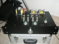
Here is the design I am shooting for and the progress so far (K16LS).


Mods completed:
- 220uF (450V), 220uF (250V), 100uF (250V) capacitors
- 6 Sonicap .22 uF (400V)
- 2 Silver Mica 33pF
Using lead free Cardas Tri Eutectic solder.
Upcoming mods:
- Stepped Attenuator - DACT imitation from eBay
- Source Selector Switch - 3 Input
- Rotary power on/off witch
- Tube Panel meters from Fair Radio
Contemplating mods:
- Power indicator led (needs DC supply, don't know how to do that yet)
- Lit up panel meter's (need DC supply too)
This is a first time that I build a tube amp.
Did not all by myself, had a big help of my 12 year old son.
He did all soldering exempt connecting the transformers, and I was mostly busy with mechanical part.
First time connected to the mains and everything was working fine. A bit of hum and noise but 70% off sorted with proper grounding. No smoke no bang...
Sound is very clear but not really warm. Missing bass, and mid range sounds to strong.
A bit disappointed to be honest. So now, need action to be taken to try to rectifier that.
I was thinking to do something of that:
1. to order tone control unit
2. to try with equalizer
3. maybe new output transformers
4. or to build new tone control unit, but that means new power supply as well (all with tubes off course).
Any advice or comment would be greatly appreciated.
You might have already seen this, but if not, below are links to modifications made to coax better sound out of the S5 kits. The links are referring to the K12M kit, but most most mods could be applied to the K16LS kit with similar results, if properly executed.
Links:
VoltSecond
Bruce
Giovanni
Links:
VoltSecond
Bruce
Giovanni
gljiva, I have had emails from others who are not pleased with the K-16LS. It seems to have the same problems as the K-8LS. Here is another person unhappy with the k-16ls tube amp
Let us know how you make out.
Let us know how you make out.
Good Day,
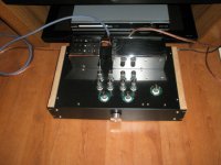
Take some time today and connected laptop to k16.
Huge noise to sorted first by disconnecting laptop from mains. After that almost complete silence.
So back to business. Used winamp with equalizer preset on techno.
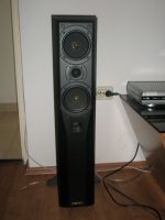
Must tell you result was perfect. Clear and soft sound. So far best results without messing around with tools.
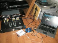
Speakers I using are mission 773. See pictures:
Take some time today and connected laptop to k16.
Huge noise to sorted first by disconnecting laptop from mains. After that almost complete silence.
So back to business. Used winamp with equalizer preset on techno.
Must tell you result was perfect. Clear and soft sound. So far best results without messing around with tools.
Speakers I using are mission 773. See pictures:
Attachments


- Status
- This old topic is closed. If you want to reopen this topic, contact a moderator using the "Report Post" button.
- Home
- Amplifiers
- Tubes / Valves
- Review of New S-5 K-16LS Kit