This amp run at 35V minimum, I suggest to use TDA2002 for amp run at 12V.
used tda2003 a lot of times,i have it and i want to replace it,i want something different
tda2002
Tragic THD +/-20% STAY AWAY!This amp run at 35V minimum, I suggest to use TDA2002 for amp run at 12V.
Tragic THD +/-20% STAY AWAY!
thd does not mean distastefullness to the listener,however other things like colorations and frequency response affects sound !!!!
TDA2003 is second best amp i have ever heard,
tda2003
If we say for the same thing (TDA2003 A.F amplifier i.c) ........I believe is one of the most terrible a.f amplifiers on the world.
Blaupunkt has used this in car radios for many years.
Sound from these radios is....just tragic.
!!!!!!!!!!!!!!!!!!!!!!!!!!!!!!!!!!!!!!!!!!!thd does not mean distastefullness to the listener,however other things like colorations and frequency response affects sound !!!!
TDA2003 is second best amp i have ever heard,
If we say for the same thing (TDA2003 A.F amplifier i.c) ........I believe is one of the most terrible a.f amplifiers on the world.
Blaupunkt has used this in car radios for many years.
Sound from these radios is....just tragic.
!!!!!!!!!!!!!!!!!!!!!!!!!!!!!!!!!!!!!!!!!!!
If we say for the same thing (TDA2003 A.F amplifier i.c) ........I believe is one of the most terrible a.f amplifiers on the world.
The problem with ANY 12 volt amplifier is that it's really only good for about 2 watts. At 4 ohms. 20% THD is what you get trying to make it put out 5. Forget 12V amplifiers if you want to drive anything but headphones.
do you have a regulated psu for this amp?(retro amp 50w)
Post #92
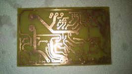
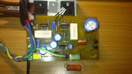
I assembled the board but i didnt had all the parts so i used some used parts and the possitive rail from a non regulated +-35V psu. i used bd139 as vas transistor and mjl21194 as output. for output capacitor i used a 1000uf/63V which is really low of capacity bad i didnt had larger one. everything will be substituted as soon as i buy parts. the sound was very good.
So mr Mile ,a few questions : as far as the psu from post 92, what do you suugest ? one with LM317 + Pass transistor ,the one at post #92 or a capacitance multiplier circuit?
for output transistors , i also have 2sc5200, 2n3773 and mjl21194 that i tested. what should i use?
for driver transistors i have bd139,bd140 ,2sb649,2sd669 ,tip31,tip32, 2sc4793,2sa1837 what should i use?
do i have to do some changes to your power /signal/ clip indicator from here? : http://www.diyaudio.com/forums/solid-state/236256-retro-amp-50w-single-supply-12.html#post3645681
Attachments
Last edited:
I assembled the board but i didnt had all the parts so i used some used parts and the possitive rail from a non regulated +-35V psu. i used bd139 as vas transistor and mjl21194 as output. for output capacitor i used a 1000uf/63V which is really low of capacity bad i didnt had larger one. everything will be substituted as soon as i buy parts. the sound was very good.
So mr Mile ,a few questions : as far as the psu from post 92, what do you suugest ? one with LM317 + Pass transistor ,the one at post #92 or a capacitance multiplier circuit?
for output transistors , i also have 2sc5200, 2n3773 and mjl21194 that i tested. what should i use?
for driver transistors i have bd139,bd140 ,2sb649,2sd669 ,tip31,tip32, 2sc4793,2sa1837 what should i use?
do i have to do some changes to your power /signal/ clip indicator from here? : http://www.diyaudio.com/forums/solid-state/236256-retro-amp-50w-single-supply-12.html#post3645681
I suggest capacitance multiplier circuit for PSU. You can use all transistor from list. On power /signal/ clip indicator use 3k3 instead 6k8.
Nice work.
Regards

I suggest capacitance multiplier circuit for PSU. You can use all transistor from list. On power /signal/ clip indicator use 3k3 instead 6k8.
Nice work.
Regards
thanks! can you suggest one??
thanks! can you suggest one??
Use MJL21194 and 2SB649/669 for drivers, use capacitance multiplier circuit from this thread:
http://www.diyaudio.com/forums/pass-labs/183482-25w-cl-amp-lateral-mosfets.html
Regards
Last edited:
i tested 2sc4793/1837 for drivers and 2sc5200 and mjl21194 for outputs. i prefer the sound of mjl21194 it seems more relaxing and smooth at high frequencies than 2sc5200. middle frequencies are very clear.as far as bass i will post as soon as i buy 4700uf output cap.
What is bias current on your amp?
thanks! can you suggest one??
there's another one here.
Capacitance Multiplier Power Supply Filter
it's simple too, just use one side of the rail.
regards.
Last edited:
What is bias current on your amp?
its 50ma .
there's another one here.
Capacitance Multiplier Power Supply Filter
it's simple too, just use one side of the rail.
thanks.good info.
there's another one here.
Capacitance Multiplier Power Supply Filter
it's simple too, just use one side of the rail.
regards.
... and use same 2n3055 as in amp.
regards
The feedback path can be implemented more elegantly
while reducing the component count and compensation
of the output caps can be easily tailored by adjusting
the ratio of the two feedback resistances.
i have made provision for such a change on my pcb but i havent test it yet. with this configuration we get rid of an electrolytic cap in signal path but with with the change of R1 in order to have half the supplu voltage at the output so does the gain change so we have to compensate by changing R3 accordingly...
i will test it in the future now i am having difficulties in choosing output transistors because both 2sc5200 and mjl21194sound really good to me....
Attachments
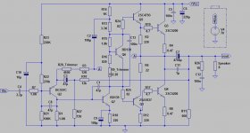
This is my updated version. vbe multiplier added,zobel network added,BD139 used as VAS transistor, feedback path changed as suggested. as i have some 2sc5200 and i want to use them,what changes do i have to do ? i tested them with the original design and everything worked fine.nice sound.but i dont have a scope to check for oscillations...
Attachments
- Home
- Amplifiers
- Solid State
- Retro Amp 50W Single Supply