Hello bix, Nice systematic way of building, marking up sch and noting hfe, etc..I measure, but dont record it
regarding C13 and R21, what thimios suggests is correct. if you dont have these handy, 4R7 & 220n should also be ok.
thimios,
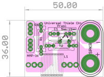
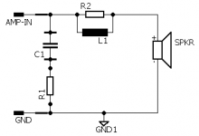
Zobel was actually an after thought , pcb was almost done by then. so incorporated whatever packages i could fit. If one wants to retain the amp by building a case, then one could add the thiele ckt (zobel + inductor) at the speaker terminal, as I very much doubt there will be ver 2 pcb.
I have a very good design posted somewhere, here it is again. J1 is default.
regards
Prasi
P.S. Because I didnt want to hear chinese music through it, I ordered 6800uF nichicons for the speaker and cornell dub's 10,000uF for the P.S.
regarding C13 and R21, what thimios suggests is correct. if you dont have these handy, 4R7 & 220n should also be ok.
thimios,
Zobel was actually an after thought , pcb was almost done by then. so incorporated whatever packages i could fit. If one wants to retain the amp by building a case, then one could add the thiele ckt (zobel + inductor) at the speaker terminal, as I very much doubt there will be ver 2 pcb.
I have a very good design posted somewhere, here it is again. J1 is default.
regards
Prasi
P.S. Because I didnt want to hear chinese music through it, I ordered 6800uF nichicons for the speaker and cornell dub's 10,000uF for the P.S.
Attachments
Last edited:
Nearly there, thanks to some help from Prasis bom and avtech23. I’m unsure what values to use for C13 and R21?
Hi Bix,
Looks like you have 12k in the R5 position?
We were discussing on here a couple of days ago about using 15k if there is unsymmetrical clipping of the output.
Do you have access to an oscilloscope?
See how you get on with 12k.
Prasi said:P.S. Because I didnt want to hear chinese music through it, I ordered 6800uF nichicons for the speaker and cornell dub's 10,000uF for the P.S.
I placed my order tonight. I too went for Cornells but 4700uf and 10,000uf.
Should be a fun build
Hello bix,
I tried to decipher from the color code for R5 but couldnt as its partly in the shadow.
It would be handy to have 15k as well as 12k and measure the mid point voltage and change R5 accordingly.
Also trimmer to be 100ohm for adjusting bias. if this isnt handy, populate a 68ohm resistor in R8 or R8' position and measure the bias. As per thimios's finding bias should be atleast 20mA for good sound.
@avtech: yes! fun build alright. Building while optimizing/adjusting the design, thanks to Mr. DIY (thimios) for guidance.
regards
Prasi
I tried to decipher from the color code for R5 but couldnt as its partly in the shadow.
It would be handy to have 15k as well as 12k and measure the mid point voltage and change R5 accordingly.
Also trimmer to be 100ohm for adjusting bias. if this isnt handy, populate a 68ohm resistor in R8 or R8' position and measure the bias. As per thimios's finding bias should be atleast 20mA for good sound.
@avtech: yes! fun build alright. Building while optimizing/adjusting the design
, thanks to Mr. DIY (thimios) for guidance.regards
Prasi
Last edited:
Hello bix, Nice systematic way of building, marking up sch and noting hfe, etc..I measure, but dont record it
regarding C13 and R21, what thimios suggests is correct. if you dont have these handy, 4R7 & 220n should also be ok.
thimios,
Zobel was actually an after thought , pcb was almost done by then. so incorporated whatever packages i could fit. If one wants to retain the amp by building a case, then one could add the thiele ckt (zobel + inductor) at the speaker terminal, as I very much doubt there will be ver 2 pcb.
I have a very good design posted somewhere, here it is again. J1 is default.
regards
Prasi
P.S. Because I didnt want to hear chinese music through it, I ordered 6800uF nichicons for the speaker and cornell dub's 10,000uF for the P.S.
Thanks Prasi, I learnt to write things down as I go after building Salas FSP. I stopped the project halfway through then came back to it four years later, life was complicated and very busy. When I started again I realised I had known idea what the component measurements were. Got it working though and it sounds great.
Thanks for the zobel design, another handy tool for my kit. Still need to read up on that one, so much to learn. Having fun being back in the hobby.
Happy you’re parts are on the way.
Use R21=10 ohm1w
C13=100nf/100 or 250v
I think that a 250v is necessary but can't fit.
Pulse expected here and Prasi must take this in account for ver. 2 pcb.
Thanks for the info thimios, much appreciated.
Hi Bix,
Looks like you have 12k in the R5 position?
We were discussing on here a couple of days ago about using 15k if there is unsymmetrical clipping of the output.
Do you have access to an oscilloscope?
See how you get on with 12k.
I placed my order tonight. I too went for Cornells but 4700uf and 10,000uf.
Should be a fun build
Hi avtech23, yes I’ve got a scope and looking forward to having a look and doing some tests. I’m still learning my way around using an oscilloscope, I’m thinking this will be a good build to learn from.
Thanks for the comments about R5, I’ll try that for sure and post some scope shots.
Hi all, can I ask what PSU setups your using?
Prasi, would this Retro Amp 50W Single Supply be something you might consider doing?
It would be great to have a high voltage adjustable regulated supply for this and other amps. Maybe this has already been done.
Prasi, would this Retro Amp 50W Single Supply be something you might consider doing?
It would be great to have a high voltage adjustable regulated supply for this and other amps. Maybe this has already been done.
Last edited:
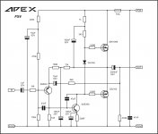
With quasi output stage, used here, you can never have ideal bias because upper driver/output pair (Darlington) requires different bias from the lower pair (Sziklai). It requires separate bias circuits for upper and lower pair. In the old times it was usual to set higher bias that suits upper pair. It's irrelevant weather you will use 10mA or 50mA because for optimum bias upper pair requires 200mA and lower 10mA.
I wonder if these issues could be solved by the following mods:
- Swap R19 from Q2's emitter to it's collector lead.
- Tie R15 to Q2's collector, make it 100R and connect a Baxandall diode in parallel with it.
Best regards!
thimios, I think used a separate psu/ bench psu for testing.
I will initially use on-board psu.
if it hums, i will use a separate crc psu with 10000uf-0.22R-10000uf.this should tame AX-6.
I have also made a layout for Apex simple cap mx and posted in Retro Amp 50W Single Supply
I will take a stab at the regulated psu.
I will initially use on-board psu.
if it hums, i will use a separate crc psu with 10000uf-0.22R-10000uf.this should tame AX-6.
I have also made a layout for Apex simple cap mx and posted in Retro Amp 50W Single Supply
I will take a stab at the regulated psu.
- Tie R15 to Q2's collector, make it 100R and connect a Baxandall diode in parallel with it.
Hi Kay,
Wondering if you can please elaborate on this one?
I am putting your suggestions into the sim to see what happens but not sure of the connections for this part..
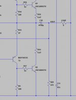
Would you be kind enough to annotate the attached screenshot?
Thanks!!
Attachments
Hi all, can I ask what PSU setups your using?
Prasi, would this Retro Amp 50W Single Supply be something you might consider doing?
It would be great to have a high voltage adjustable regulated supply for this and other amps. Maybe this has already been done.
something along these traces?regards
Prasi
Attachments
I wonder if these issues could be solved by the following mods:
- Swap R19 from Q2's emitter to it's collector lead.
- Tie R15 to Q2's collector, make it 100R and connect a Baxandall diode in parallel with it.
Best regards!
Kay,
Of course that Baxandall diode solves this problem and shows how great engineer he was! I did not want to complicate things with such info when the PCB is already done but implementing this mod would make this amp even better.
Would you be kind enough to annotate the attached screenshot?
Of course! Make R15 100 ohms, disconnect it's upper leg from the output bus and connect it to Q2's collector (downside of R19). Then get a 1N4004 (or something like that) in parallel with this resistor, cathode to T3's emitter.
I'm curious of your sim results!
Beste regards!
regards
Prasi
Nicely done my friend, you’re very clever.
Of course! Make R15 100 ohms, disconnect it's upper leg from the output bus and connect it to Q2's collector (downside of R19). Then get a 1N4004 (or something like that) in parallel with this resistor, cathode to T3's emitter.
I'm curious of your sim results!
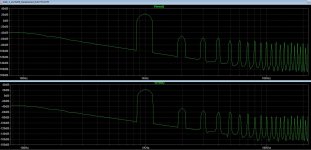
Here we go, screenshot of the FFT and sim file to play with.
Top window is for comparison - this version uses 2SC5200 outputs, has 15K in R5 for voltage centering and 3k6 in R6 to reduce gain to around 25. The comparison THD is 0.027, the modded version is 0.0364.
There is a bit of spikiness to the FFT with the mods but I don't know enough about spice yet to know if it is a good or bad thing
Attachments
Nice, many thanks apexaudio. I will try the circuit soon. And what do you think of it's possible quality compared to the old circuit by Robert Penfold posted a few pages back? I've wanted to remove the output cap by using split power supply. Could you please provide such circuit with single ended input and split power supply?
BTW, what is the voltage supply range?
Last edited:
Thanks for that Simulation, avtech23!
If I get it right, I'd tend to say the following:
- The modification as suggested by me does little or nothing.
- If we look closer, even order harmonics are decreased, odd harmonics are increased a tiny bit each.
So I tend to recall my suggestion ;-).
Best regards!
If I get it right, I'd tend to say the following:
- The modification as suggested by me does little or nothing.
- If we look closer, even order harmonics are decreased, odd harmonics are increased a tiny bit each.
So I tend to recall my suggestion ;-).
Best regards!
- Home
- Amplifiers
- Solid State
- Retro Amp 50W Single Supply