
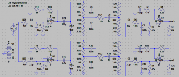
Mooly, I also based my recommendation on simulation and I get very different results, see attached. As I said the difference at 20Hz is ~0.4dB, even will all three coupling caps changed to 2u2. For the power amp I use an opamp but with the same feedback network so the response should be pretty close. Can you see something wrong with my sim?I personally wouldn't change the couplings caps to a lower value. Its not just the response below a certain point that is affect, it also affect the response above the nominal roll off point as well. C505 is 100uf because the opamp has to drive the variable impedance of the tone network. C605 is also 100uf.
There is nothing wrong with electrolytics used (correctly) as coupling caps.
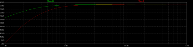
This shows the effect on response (on an amp with your feedback network values plugged in) of going from 100 uf to 2.2uf for just C605. This shows response from 1Hz to 1kHz.
Cheers,
Cabirio
Attachments
OK, the base current is very low when you use a Darlington so 1/4W will be fine for Rb but the current is handled by the unspecified dropping resistor at the collector, not the base. A 600R 24V relay coil for example, will draw 40mA and the dropping resistor at the collector will need to dissipate the 13V/40mA difference or 0.3W. I'd fit a 330R 1W carbon or metal film, spaced a little from the board......The supply voltage is 37V....
Last edited:
A BJT has current gain according to the Hfe of the device, which is high for BD681 - minimum 750. The base current contribution to 40 mA emitter current would then be <50uA. You would fit a base resistor that could supply the necessary current worst case, when the power supply was low for any reason, such as in local supply fluctuations, or during rail voltage sag at full power output. 35V/50uA (allow for 2 emitter junctions) would equate to ~ 680k but you could need a smaller value to ensure the device remained fully on. Not certain what that should be but Mooly has the relay experience - perhaps he'd like to comment/correct ")
Can you see something wrong with my sim?
Cheers,
Cabirio
It looks fine
I just showed the result of changing only C605 in the power amp (because I think that got mentioned a while back) and so as an example it gave the most dramatic illustration of what happens. Your changing all the others except C605 I think, so less of an effect but obviously still significant. C16 in your sim could have a variable effect depending on the tone settings.
Not certain what that should be but Mooly has the relay experience - perhaps he'd like to comment/correct
Well you can't beat empirical methods sometimes. Start with say 22k to ensure the device is fully saturated (by noting the voltage across C and E when the relay is on). Now increase the resistor to say 100k. Is it still saturated ? If so then go to 220k and check again and so on. When the transistor starts dropping out of saturation, half the value of the base resistor to ensure its going to work correctly under all conditions (such as freezing cold).
A darlington makes the addition of a high value resistor across B-E mandatory.
I'm also wondering... as you do... that adding a relay makes the introduction of a simple power on delay possible to eliminate switch on thumps and so on.
So just do it experimentally? I can work with that, just wanted to do the engineering on it for my own knowledge. Now that hFE value, where did you get that? I knew I was missing that, but the data sheet only shows a minimum value of 1, and there was no graph either.
According to the datasheet that transistor drops 2.5V across BE, is that correct?
Is the resistor across base and emitter to pull up the base when the switch is off?
Edit: that hfe value was looking at me the whole time.
According to the datasheet that transistor drops 2.5V across BE, is that correct?
Is the resistor across base and emitter to pull up the base when the switch is off?
Edit: that hfe value was looking at me the whole time.
Last edited:
Calculating... hFE quoted as 750 minimum at 1.5 amps collector current. Lets call it 500 for good measure and operating at cold temperatures.
The base-emitter turn on volts can be discounted because of the high supply voltage, in other words its not worth accounting for. So we need 0.2/500 which is 0.0004 amps of base current. Converting that to a resistor and we get 37/0.0004 which is 92.5k. So a safe value to cover all possible conditions from the poles to the equator would be 47k.
Yes, the resistor across B and E is to stop the relay chattering due to any leakage and stray pickup on the base. Something like a 220k is fine.
The B-E voltages sound high but that is what they quote... I wouldn't expect that if the transistor were made from two discrete devices that you would see that.
Ok, I've reread my post and I see how it can be confusing. I wasn't proposing to replace C605, just explaining how it can introduce distortion and how this can be minimized by high-pass filtering the signal before the power amp by reducing the value of the coupling caps. I did try the sim with the tone controls at the extremes and the effect is the same, 0.4dB loss at 20Hz.It looks fine
I just showed the result of changing only C605 in the power amp (because I think that got mentioned a while back) and so as an example it gave the most dramatic illustration of what happens. Your changing all the others except C605 I think, so less of an effect but obviously still significant. C16 in your sim could have a variable effect depending on the tone settings.
Of course another option is to make C605 itself bigger and/or use a good quality Nichicon Muse ES, as I think Ian suggested for the coupling caps. Some impressive measurements here.
Cheers,
Cabirio
I'm thinking about this power on delay now. This should be an inherent characteristic of the relay coil right? It behaves like an indicator. Right?
That is, if my schematic was reconfigured so the the coil was energised for the speakers to output, not phones.
Sort of
the relay coil needs to be energised to connect the speakers, that is the default state. We could I think delay the relay operation quite easily though. Ok, I've reread my post and I see how it can be confusing. I wasn't proposing to replace C605, just explaining how it can introduce distortion and how this can be minimized by high-pass filtering the signal before the power amp by reducing the value of the coupling caps.
No problem. Don't know what you think but, I would probably still suggest sticking to the original design values for all these coupling caps. Not least because it would look neat and tidy and the small caps are less prone to stray pickup.
I was thinking about the Wima MKS that sanguinicus mentioned, the MKS2 series 2u2/50V have 5mm lead spacing and 7.2x5mm LxW, so they should fit in nicely...No problem. Don't know what you think but, I would probably still suggest sticking to the original design values for all these coupling caps. Not least because it would look neat and tidy and the small caps are less prone to stray pickup.
I was thinking about the Wima MKS that sanguinicus mentioned, the MKS2 series 2u2/50V have 5mm lead spacing and 7.2x5mm LxW, so they should fit in nicely...
Yes, they should be do-able. I must admit I'm not a believer for the most part when it comes to caps in the signal path
although its nice to eliminate electros.-------------------------------------------------------------------------------------
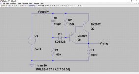
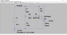
OK, a quick cobble together of a delayed start that also drops out before the supplies totally collapse. Both versions are very tweakable although the FET version is the preferred option. The first is a Darlington (discrete). I've not put the back emf diode on either.
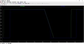
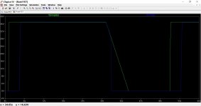
The supply comes up in around 200ms, its on for a few seconds and then its turned off. You can see the relay voltage delayed at start up and also how it drops out before the rail collapses.
Attachments
Sticking with the original plan and replacing the electrolytics of the same value.
As for the soft start feature, I think that's complicating things now, I was hoping to do it with the headphone relay, so I might leave that for now.
I should be getting parts in a few weeks. I was hoping to start with the headphone circuit but I've only got 24V SPDT relays lying around.
As for the soft start feature, I think that's complicating things now, I was hoping to do it with the headphone relay, so I might leave that for now.
I should be getting parts in a few weeks. I was hoping to start with the headphone circuit but I've only got 24V SPDT relays lying around.
It does use the headphone relay
Ah I kind of get how that works. The problem is my relays are only spdt. I could use two...
Yes you could use two. In fact knowing what we know about relays, you could probably wire the coils in series and so avoid needing a limiting resistor. Most relays pull in at around 60% (or less) of the nominal coil voltage... obviously you would have to try it but I can't see any problem there.
- Status
- This old topic is closed. If you want to reopen this topic, contact a moderator using the "Report Post" button.
- Home
- Amplifiers
- Solid State
- Restoring Rotel RA-810A