Yes. You said you wanted to replace coupling electrolytics with film caps, which I think is a good move, but were concerned about the cost. Each of those caps, together with the resistance to ground that follows it, is a high pass filter with a cutoff (-3dB) frequency of 1/(2*PI*R*C). The same goes for the cap and resistor in the ground leg of the power amp feedback, C605 and R609 (in this case, 1/(2*PI*470*100u) = 3.39Hz). Both C501 and C601 are followed by a 47k resistor to ground, so with the stock value of 10u, their cutoff freq. is 0.34Hz. It doesn't have to be that low in order not to affect significantly the overall frequency response, which means that you can use smaller values, like 2u2 as I proposed.That's a lot to absorb. At this stage I'll just substitute like for like parts. What is the advantage of the substitutions you are suggesting if the end result is the same? Save cost and space on the board for smaller parts?
As for C605, even if it doesn't look like it, it is very much in the signal path. Electrolytic caps introduce distortion when the AC voltage they see is significant. The frequency at which this happens is the frequency at which the reactance of the cap is of the order of the resistor that it has in series, 3.39Hz in this case.
Now, if you restrict the LF response before the input of the power amp with a high pass filter whose cutoff frequency is higher than 3.39Hz, you make sure that the FR will have fallen off sufficiently at that frequency that no significant signal will be present across C605. A rule of thumb that fellow member AndrewT has come up with is to have a high pass filter somewhere before the power amp whose cutoff freq. is higher than the one due to C605 by sqrt(2). By making C505 (which is followed by a 47k resistor to ground in parallel with the passive tone circuit = ~13k6) also 2u2, you get a cutoff freq. of 5.32Hz, which satisfies the rule of thumb of being > 3.39*sqrt(2). This has an effect on the overall frequency response where at 20Hz you get a drop, compared to the stock values, of 0.4dB. Whether this is acceptable for you depends on personal taste, how low your loudspeakers go, etc.
Cheers,
Cabirio
Actually do you have any suggestions on how to mute the speakers with phones in?
I'm just looking at the RA810 diagram now. That's nuts in it not having a switched output.
Just thinking aloud... so a normal headphone socket of the kind you get anywhere has 6 terminals with the audio and ground feeding into one side, and with nothing plugged in they carry across to the other side. Insert the plug and the 'other side' contacts are isolated.
So you could have say a PNP darlington driving a relay and with the base tied through the ground pin on the socket via say a 220k. Insert the phones and the ground is lifted and the PNP device turns off isolating the relay. Remove the phones and the transistor is on pulling the relay in.
Two components at a basic level plus a relay. Transistor could be bolted to the chassis.

Yes. You said you wanted to replace coupling electrolytics with film caps, which I think is a good move, but were concerned about the cost.
Cheers,
Cabirio
Thanks for the very comprehensive response. I'll analyse the cost of these components and report back.
Anyone have anything to say about replacing the carbon comp resistors with metal films?
Mooly replaced the opamp in his 820 in the thread he linked, is this a worthwhile upgrade? Those opamps cost a bit, but will I be blown away?
You need something that can withstand the supply voltage of one rail (so at least 60 volt for a good margin). The resistor needs to be low enough to fully turn on the transistor so that there is no power loss. The relay needs to have (ideally) a 24 volt coil (higher voltage the better). You would add a series resistor to get the coil voltage correct. A diode (1n4004 type) across the coil to absorb back emf and that's it. Purists would add a further resistor (say 47k) across B and E of the transistor to ensure the base isn't floating such as would happen when 'phones were plugged in.
The OPA2604 is one of the more 'colourful' opamps but in a really good way. You would only know by trying it and if you don't use the phono input then only the one IC needs swapping. It runs at relatively high gain here which means that there should be no issues in doing a straight swap.
The OPA2604 is one of the more 'colourful' opamps but in a really good way. You would only know by trying it and if you don't use the phono input then only the one IC needs swapping. It runs at relatively high gain here which means that there should be no issues in doing a straight swap.
In your doodle you drew a normally open contact. The switched jacks available are mostly normally closed.
Also, I believe the ground plane in this amp is -37V, do I just treat this like a conventional ground?
EDIT: I reread what you posted, so the switch is indeed normally closed and the phone jack opens the contact. Got it. Working on this now. So the relay is energised when the speakers are on. That is, headphones out. Still need an answer on that negative ground.
Last edited:
If i did the above, so that the coil is energised when the phones are in, will that mess around with the ground of the headphones being connected to the resistor and transistor? Or should I go with the original plan so the coil is energised when the phones are out?
This is what I have so far. I havent gone through my box of bits yet so havent selected a transistor. Also the current limiting resistor between the collector and coil is missing.
This is what I have so far. I havent gone through my box of bits yet so havent selected a transistor. Also the current limiting resistor between the collector and coil is missing.
An externally hosted image should be here but it was not working when we last tested it.
Last edited:
You only have a 20 minute or so window to edit posts.
That basically correct. We would just use one rail for this, the plus 37 volt one and the main audio ground. Nothing connects to the -37 volt rail.
Ohhhh, so there's an actual 0V ground. I suppose I should buzz out the circuit and find it. Well I think I have enough information for now. I'm going to research those smaller film caps and see if I want to pony up the money for them. I might even have a 24V relay here so i can start fiddling around with that while the rest of my parts arrive.
EDIT: The most cost effective film caps are polyester. Polyprop are so prohibitively expensive. Will I get away with Polyester, or should I just stick to the electrolytics?
Last edited:
Definitely a groundIt is the speaker negative, which connects to the junction of the two main reservoir caps in the power supply. You would use the existing headphone ground point as that should ensure the best ground point to avoid hum and noise.
Thanks for that, I thought those were the negative rail.
Yes. You said you wanted to replace coupling electrolytics with film caps, which I think is a good move, but were concerned about the cost.
Cheers,
Cabirio
So basically the four coupling caps in each channel (C501, 505, 601, 605) can all be 2u2F?
My speakers don't get anywhere near 20Hz so I'm not concerned about any loss in the LF that low. It's only slightly more expensive so I'll go with film.
Last edited:
I personally wouldn't change the couplings caps to a lower value. Its not just the response below a certain point that is affect, it also affect the response above the nominal roll off point as well. C505 is 100uf because the opamp has to drive the variable impedance of the tone network. C605 is also 100uf.
There is nothing wrong with electrolytics used (correctly) as coupling caps.
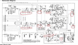
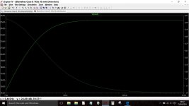
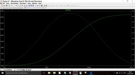
This shows the effect on response (on an amp with your feedback network values plugged in) of going from 100 uf to 2.2uf for just C605. This shows response from 1Hz to 1kHz.
There is nothing wrong with electrolytics used (correctly) as coupling caps.
This shows the effect on response (on an amp with your feedback network values plugged in) of going from 100 uf to 2.2uf for just C605. This shows response from 1Hz to 1kHz.
Attachments
I would
A tip... if you do change anything like opamps (and even if you don't), then its worth measuring the DC voltage across the coupling caps (which will be minimal, perhaps only a few millivolts) and fit any replacement caps to match the polarity measured, which may be in conflict to that marked on the board.
A tip... if you do change anything like opamps (and even if you don't), then its worth measuring the DC voltage across the coupling caps (which will be minimal, perhaps only a few millivolts) and fit any replacement caps to match the polarity measured, which may be in conflict to that marked on the board.
Someone take me back to school.
So I'm working on this headphone switching circuit and I managed to find a BD682G PNP in my parts bin. I'm having trouble calculating the base resistor.
If the supply voltage is 37V, maximum emitter-base voltage is 5V, so if I work on 3V (saturation is at 2.5V) and calculate thus:
37-3=34V drop across the base resistor
Say, on current for the base is .02A
R=V/I
R=34/.02
R=1700
so I should be able to use a 2k resistor for the base resistor. If I calculate power, I'd need about a 1W resistor.
Or do I have this monumentally wrong?
Just making sure I have everything correct. I don't have a power supply so i can't test this on the bench.
- Status
- This old topic is closed. If you want to reopen this topic, contact a moderator using the "Report Post" button.
- Home
- Amplifiers
- Solid State
- Restoring Rotel RA-810A