The method explained is very similar to that used by my PIC based meter... it basicaly calculates like that with the only problem being the max integer that will fit in the PIC. limiting it to somewhere around 800nf...
Maybe someday if I get a grip on these things a little better I will play with it some more... at the moment it does at least have a calibrate setting where you short the probes and hit reset, it will than measure the internal inductance as 0h.
I also need to adjust the oscillator and software as it is working around 5kHz which may be a bit high for speaker inductors, will aim for about a fifth of that.
You may also want to look at
LC Determination by Resonant Frequency Measurement
http://www.cappels.org/dproj/lgm/lgm.html
Remember, at 600 Hz, and for a 10 ohm resistor, the difference between absolute unobtainable perfection and 50uH of stray inductance, is only about 1 degree of phase shift. Other than that tiny phase shift, they look exactly the same. Thus the difficulty of making the measurement at low frequencies. The GR 1608 bridge, which has a compensation cap on the Rs bridge to measure Q of resistors, doesn't see much at 1 kHz, because the Q is so low. The knob is just barely off the peg. IMO, if you want to examine this sort of thing, you have to build a bridge with low strays, and make the measurement at a much higher frequency, say 100 kHz or higher.
NoNordic said:Is an inductor basicaly a capacitive resistor? I.e. inductance is related to capacitance per ohm?
Inductance is the relationship between the energy stored within a magnetic field and the current responsible for creating that field.
The equation is E = 1/2 L I^2.
So:
L = (2E) / I*I
For a capacitor, it is E = 1/2 C V^2.
Cheers, John
Guys;
Try setting up the meter to measure the resistor...then, after the reading, short the resistor without moving anything.
The difference will be the inductance caused by the turns of the resistor.
The shorted reading will be the combo of the meter residual, and the geometric inductance caused by the loop.
Check your manuals, as specific meters may take issue with Lp vs Ls, depending on the reactance being tested. The HP 4263A for example, recommends Rs when the reactance of the inductor falls below 10 ohms, and Rp when reactance is above 10k ohms. Course, in between, the say "follow the manufacturer's recommendations"...just great..
Cheers, John
Here's a Usenet discussion thread that I just stumbled across, that might contain some relevant points, about inductance meters:
http://groups.google.com/group/sci....read/thread/dc460d5faa9b82ee#df9a337029d64e16
(Yes. The "Winfield" guy, there, is the co-author of "The Art of Electronics". He contributes, regularly, to that group.)
http://groups.google.com/group/sci....read/thread/dc460d5faa9b82ee#df9a337029d64e16
(Yes. The "Winfield" guy, there, is the co-author of "The Art of Electronics". He contributes, regularly, to that group.)
gootee said:Here's a Usenet discussion thread that I just stumbled across, that might contain some relevant points, about inductance meters:
http://groups.google.com/group/sci....read/thread/dc460d5faa9b82ee#df9a337029d64e16
(Yes. The "Winfield" guy, there, is the co-author of "The Art of Electronics". He contributes, regularly, to that group.)
Strangely enough, nobody within that discussion answered the op's question accurately. The question was.."why at two different frequencies, did the inductor measure differently, hf inductance being 21 times less than the 1Khz measurement."
The inductance being measured will certainly go down with frequency. That is because of the eddy currents within the core. In addition, the parasitics will begin to play more of a role as the core reacts differently at the higher freuencies.
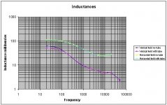
I encounter this problem all the time at work. While the magnets are destined for use at DC (with some low level capability at 100 hz), it is not possible to measure the DC inductance. So I have to run a plot, and extrapolate to dc.
With room temp magnets, the iron dominates, even if it's laminations. With superconducting magnets, a copper support tube or aluminum heatsheild will cause the inductance at 100 hz to measure low. Eddies.
Here's a typical room temp magnet; note the drop in inductance as frequency goes up, and the laminations are less than 1mm in thickness. The magenta and blue graph will of course, merge as frequency goes further down, I just didn't have a meter capable of below 20 hz operation. But the effect of the inclusion of the metal with it's eddies is clear.
Cheers, John
ps..oh, btw. the horiz field is a different magnetic path, so does not have as much iron within the flux path..that is why it does not drop it's inductance quite as much as the vertical. It also doesn't see the same cross section of the "tube" I put in it's way as the vertical, so the horiz inductance doesn't change as much as the vertical one. The vertical flux is normal to the aluminum beam tube, horizontal is tangential.
Attachments
Here are some impedance curves of different inductors of the same value. As you can see, not all inductors are made equal. I would assume that inductance in resistors to be somewhat similar.
An externally hosted image should be here but it was not working when we last tested it.
An externally hosted image should be here but it was not working when we last tested it.
In the top chart was one air core and two cored inductors. All measured 2mH on a meter.gootee said:Hi soongsc,
What type of inductors were they and what was the rated inductance value? And what did you use to measure the impedance?
In the bottom chart, an additional cored inductor was added. All inductors had #14 solid wire.
SoundEasy was used to make the measurements. The most interesting I found was the impedance phase between and aircore and cored inductor.
Marchel,
I think that the general consensus is that the inductance in the resistor is negligible compared to that of the driver. Most of the inductance measurements which have been done with suitable equipment show very low inductance (< 0.005 mH) for standard wire wound resistors.
I will post my measurements shortly.
Regards,
David
Here are the results of some measurements I made today.
-Measurements were made using the HP 4192A Impedance Analyzer (Calibrated this year).Three measurement frequencies were used 100Hz, 1kHz, 10kHz.
-Signal voltage was 1VRMS.
-The series equivalent circuit model was used for calculations.
-I used test leads to clip on each part which in themselves had some inductance. If I were to repeat the test more rigorously, I would set up a fixture to hold the parts. (This was a lunch break project).
-The analyzer was zeroed at each frequency to neutralize this inherent inductance, and each component was tested at this frequency before moving to the next frequency. This means that while comparison of parts at the same frequency is valid, comparisons of measurements - even of the same part - at different frequencies is not necessarily accurate.
-I let the analyzer auto-range, which in retrospect might have been a mistake. There are two questionable measurements for the higher value resistors, I would like to measure those again with manual ranging set to get higher resolution.
Conclusions? I would like to repeat these measurements with a fixture, but I think I've seen enough. I personally will not be bothering to order non-inductive parts in the future. Even for tweeter circuits.
Regards,
David
-Measurements were made using the HP 4192A Impedance Analyzer (Calibrated this year).Three measurement frequencies were used 100Hz, 1kHz, 10kHz.
-Signal voltage was 1VRMS.
-The series equivalent circuit model was used for calculations.
-I used test leads to clip on each part which in themselves had some inductance. If I were to repeat the test more rigorously, I would set up a fixture to hold the parts. (This was a lunch break project).
-The analyzer was zeroed at each frequency to neutralize this inherent inductance, and each component was tested at this frequency before moving to the next frequency. This means that while comparison of parts at the same frequency is valid, comparisons of measurements - even of the same part - at different frequencies is not necessarily accurate.
-I let the analyzer auto-range, which in retrospect might have been a mistake. There are two questionable measurements for the higher value resistors, I would like to measure those again with manual ranging set to get higher resolution.
- 1.5 Ohm Dayton Non-Inductive Wire-Wound 10W
0.10 kHz 1.505 Ohm 0.0002 mH
1.00 kHz 1.502 Ohm 0.0003 mH
10.0 kHz 1.500 Ohm 0.26 uH
- 1.0 Ohm Madisound Wire-Wound 15W
0.10 kHz 0.984 Ohm 0.001 mH
1.00 kHz 1.502 Ohm 0.0009 mH
10.0 kHz 1.503 Ohm 0.72 uH
- 2.0 Ohm Madisound Wire-Wound 15W
0.10 kHz 1.968 Ohm 0.0001 mH
1.00 kHz 1.502 Ohm 0.0004 mH
10.0 kHz 1.503 Ohm 0.33 uH
- 14 Ohm Madisound Wire-Wound 15W
0.10 kHz 13.99 Ohm <0.01 mH * questionable result
1.00 kHz 13.99 Ohm 0.003 mH
10.0 kHz 14.00 Ohm 0.0023 mH
- 25 Ohm Madisound Wire-Wound 25W
0.10 kHz 24.39 Ohm <0.01 mH * questionable result
1.00 kHz 24.37 Ohm 0.004 mH
10.0 kHz 24.37 Ohm 0.0032 mH
Conclusions? I would like to repeat these measurements with a fixture, but I think I've seen enough. I personally will not be bothering to order non-inductive parts in the future. Even for tweeter circuits.
Regards,
David
Marchel,
I think whether the cast resistor is okay or not depends on performance of the driver. If the driver itself does not show fast decay in the waterfall plots, then maybe you can; if the driver decays very fast, I would at least use wire wound resistors. It's best to just try yourself to see if you are satisfied or not.
I think whether the cast resistor is okay or not depends on performance of the driver. If the driver itself does not show fast decay in the waterfall plots, then maybe you can; if the driver decays very fast, I would at least use wire wound resistors. It's best to just try yourself to see if you are satisfied or not.
I think an easy way to measure the inductance of a WW resistor (aside from having a vector network/impedance analyzer) would be to hook it up in a voltage divider circuit with an equivalent non-inductive resistance like below
INPUT(low impedance Z << R, i.e. SS amplifier)
|
|
WW resistor of value R
|
|-> output (measurement)
|
|
NI resistor of value R
|
|
GND
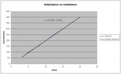
Adjust input frequency (f) until output amplitude is 1/3 the value of the input amplitude (guessing this will be much higher than the audio band), then the reactance of the WW will be X = R ohms. Then L=R/(2*pi*f).
I have an LCR meter that also shows incorrect measurements with low Q inductances, like WW resistors. Not a design flaw, just something to keep in mind.
There are some wirewound resistors wound in fashion to cancel magnetic fields, but they are usually special order (called 'Ayrton-Perry' type winding)
INPUT(low impedance Z << R, i.e. SS amplifier)
|
|
WW resistor of value R
|
|-> output (measurement)
|
|
NI resistor of value R
|
|
GND
Adjust input frequency (f) until output amplitude is 1/3 the value of the input amplitude (guessing this will be much higher than the audio band), then the reactance of the WW will be X = R ohms. Then L=R/(2*pi*f).
I have an LCR meter that also shows incorrect measurements with low Q inductances, like WW resistors. Not a design flaw, just something to keep in mind.
There are some wirewound resistors wound in fashion to cancel magnetic fields, but they are usually special order (called 'Ayrton-Perry' type winding)
just tried connecting a pair of 100 ohm WW resistors placed physically side by side in & out of 'phase' - result, no difference (although it's probably beyond the capacity of my cheapo meter to give a reliable reading at this level of resolution - should keep the 'tweakers' over at AA busy for aeons though )")
In order for the inductances to cancel, the magnetic fields would have to equally oppose each other. This would require that the windings be closely coupled and appropriately wound ie the 'Ayrton-Perry' winding style. Although I would definitely get a kick out of a hoax post to AA, just to observe the resulting tom-foolery!
- Status
- This old topic is closed. If you want to reopen this topic, contact a moderator using the "Report Post" button.
- Home
- Loudspeakers
- Multi-Way
- Resistor Inductance