peter_m said:
I don't have experience with LCR meters but I'm sure these things can be calibrated to ZERO... or your leads are rolled up or near a metal object... Just my modest thoughts!
Good thoughts. With a good meter, the autocal function can be used to remove the leads. But it requires shorting the leads, and not disturbing them prior to measurement.
I've done such to get the error component down to 250 picohenries, but I gotta tell ya, it's a beech.
bastek said:Your measurement is not far off mine:
3.3 © 60¼h
5.1 © 100¼h
8.2 © 160¼h
12.5 © 250¼h (0.25mh)
20 © 400¼h (0.4mh).
I don't see any errors.
You have -5 uH of zero offset. Not too shabby, by any means.
gootee said:Sorry. On second thought, it's not terribly high.
Concur. I was wondering why you said such.
If we assume a rough estimate of 25 nH per inch of wire, it would only take 10 feet of wire to get to 3000 nH = 3 uH = .003 mH. So it's right in line with what might be expected for two 5-foot probe wires.
Why would one assume 25 nH per inch? The size and geometry of the loop will dominate the error inductance.
If you want to remove the leads, use a wire of the same physical length as the resistor being tested, and measure that inductance.
Subtract that from the reading of the resistor.
Cheers, John
bastek said:
Your measurement is not far off mine:
3.3 © 60¼h
5.1 © 100¼h
8.2 © 160¼h
12.5 © 250¼h (0.25mh)
20 © 400¼h (0.4mh).
I don't see any errors.
I guess my Greek characters don't show well on your screen.
OK, just as a "sanity check" for myself:
Your 10W 20-Ohm resistor would be rated for a maximum current of sqrt(10/20) = 0.7071 Amp. I looked in the mouser.com catalog, to check the physical sizes of inductors that are about 400 uH (0.4 mH) that are rated for 0.7 Amp or so.
I found one that is 390 uH and rated for 0.64A saturation current (0.4A max suggested) that measures 0.7 inch long and 0.275 inch diameter.
I found another one that is 500 uH, with IDC max 2 Amps, that measures 1.25 inches long and 0.56 inch diameter.
The typical rectangular cement 10W wirewound power resistor measures 49mm x 10mm x 9mm, which is about 1.93 inches x 0.4 inch x 0.35 inch.
So it is now more obvious that, based on size alone, it is easily possible to have that much inductance.
I was rather hoping that the inductance would be lower, especially after seeing claims for certain other types of power resistors that say the inductance for low-Ohm values is negligible. But, apparently, for some "sand-cast" (same as "cement"??) resistors, at least, that is not the case.
bastek said:I guess my Greek characters don't show well on your screen.
They showed up perfectly. I don't know why they didn't copy into my post..
Cheers, John
jneutron said:
Good thoughts. With a good meter, the autocal function can be used to remove the leads. But it requires shorting the leads, and not disturbing them prior to measurement.
I've done such to get the error component down to 250 picohenries, but I gotta tell ya, it's a beech.
You have -5 uH of zero offset. Not too shabby, by any means.
Why would one assume 25 nH per inch? The size and geometry of the loop will dominate the error inductance.
If you want to remove the leads, use a wire of the same physical length as the resistor being tested, and measure that inductance.
Subtract that from the reading of the resistor.
Cheers, John
Sorry. I guess I don't understand. Even with no loop, a straight wire has inductance. The 25nH/inch number is just a commonly used ballpark guesstimate, for smallish wires and pcb traces, until the actual geometry can be used to get a better estimate.
gootee said:Sorry. I guess I don't understand. Even with no loop, a straight wire has inductance.
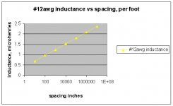
Actually, a straight wire has infinite inductance, a consequence of integration of the 1/r field and the increasing area of integration.. The reason it does not measure as infinite, is because the return current cancels out the bulk of the external field. I attached a chart of inductance vs spacing for a #12 wire pair. As can be seen, the inductance continues with distance. Course, to get the inductance large requires a rather large universe, eh?
")
gootee said:The 25nH/inch number is just a commonly used ballpark guesstimate, for smallish wires and pcb traces, until the geometry is used to get a better estimate.
Yup. However, it is a ballpark figure used within the constraints of a ground plane and PCB work. For a wire that is not poised above a ground plane which serves as the current return path, as the current discussion entails, that number cannot be used.
Cheers, John
Attachments
jneutron said:
Actually, a straight wire has infinite inductance, a consequence of integration of the 1/r field and the increasing area of integration.. The reason it does not measure as infinite, is because the return current cancels out the bulk of the external field. I attached a chart of inductance vs spacing for a #12 wire pair. As can be seen, the inductance continues with distance. Course, to get the inductance large requires a rather large universe, eh?
Yup. However, it is a ballpark figure used within the constraints of a ground plane and PCB work. For a wire that is not poised above a ground plane which serves as the current return path, as the current discussion entails, that number cannot be used.
Cheers, John
Thanks John. I understand, better, now.
Apparently I'm not thinking very clearly, today. [However, in my (mind's) defense, it has been quite a few years since I thought I knew more than a little about the details of electromagnetics.]
gootee said:[However, in my (mind's) defense, it has been quite a few years since I thought I knew more than a little about the details of electromagnetics.]
Consider yourself one of the lucky ones.
I'm still thinking about the resistance vs inductance that bastek posted.
Ran the numbers in excel, it shows as extremely linear, with a y axis intercept of -5uH, equation is L (uh)= (20.3 R )- 5...sorry can't post the plot as a jpeg, ..
The number of turns doesn't scale with the resistance, so it's a combo of guage and turns per inch. L scales as the square of the turns, so double the resistance should be 40% more turns, and probably 70% of the wire cross section...as a first guess.
Cheers, John
A picture is worth a thousand words.
Mills 10 ohm resistor.
Mills 10 ohm resistor.
An externally hosted image should be here but it was not working when we last tested it.
And a Dayton sand cast 10 ohm resistor.
An externally hosted image should be here but it was not working when we last tested it.
Ever curious and not wanting to be left out, I just dredged up some old sand resistors, a TRW 7 ohm and a Radio Shack 40 ohm. Both 5W. They look purely resistive on my low frequency bridges, so I put them on the vector impedance meter for a HF measurement where obvious phase shift could be seen. At 3MHz, the 7 ohm job read 9 ohms and +30 degres. It was probably a little high to begin with, but that implies an Ls of 238 nanohenries and an Lp of 955 nanohenries. Remember to always specify which model you're using, as it makes a large difference in this case. The 40 ohmer read 44 ohms and +28 degrees, giving 1 microhenry Ls and 5 microhenry Lp. I don't believe either of these were specially non-inductively wound, and IMO inductance in low value resistors probably isn't much of an issue. I also have some cylindrical low value resistors with very obvious solenoid windings, and I'll measure those at some point.
Just to double-check, I pulled out several different power resistors and measured inductance directly (Leader LCR-740 bridge). A 10R Dale RH-25 showed lower inductance than I could measure. The 5R 15W no-name sandcast I measured before came out the same as before, about 50uH. Some other no-name sand-cast units (7R5, 15W) measured 12uH. A 4R7 IRC PW5 sandcast measured 26uH.
So, they seem to be all over the place, depending on manufacturer and internal construction.
So, they seem to be all over the place, depending on manufacturer and internal construction.
Here's a comparison between a Digikey Metal film, 243R 1/4W, and a Dale RN60 243R, 1/4W. Phase is the lighter of the two screen shots. The network analyzer was baselined before each shot. The test setup consists of short lengths of RG58 to BNC connectors on a piece of double-clad PCB material:
DK Metal Film
RN60
DK Metal Film
An externally hosted image should be here but it was not working when we last tested it.
RN60
An externally hosted image should be here but it was not working when we last tested it.
The inductance is not terribly frequency dependent, so you need a high frequency to reliably measure it. Bottom line is it probably doesn't amount to a hill of beans at any audio frequency. It's more illuminating to look at phase vs. frequency, which is why those network analyzer plots are so nice, but it can all be converted to whatever system you like to work with.
Conrad's Handy Impedance Converter
Conrad's Handy Impedance Converter
In the interest of science and having nothing better to do, I put my 40 ohm resistor in a vise and crushed it. Felt great! It's made up of a wound fiber core of some sort, with 22-23 turns of 0.0037" diameter wire evenly spaced over 0.4" between the end caps. The length of the wire is about 9". The end caps are just little brass caps, crimped on the wire. Not terribly confidence inspiring in terms of stability or reliability. Both the end caps and wires are non-magnetic, but the actual resistance wire is strongly magnetic. Makes me feel far better about my non-magnetic, non-inductively wound, solidly soldered, diy Manganin resistors.
You guys are having too much fun.
Well Sy, with values like that, I could use them as output inductors in my Class-D amps. DCR would be a bit high.....
SY said:Some other no-name sand-cast units (7R5, 15W) measured 12uH. A 4R7 IRC PW5 sandcast measured 26uH
Well Sy, with values like that, I could use them as output inductors in my Class-D amps. DCR would be a bit high.....
Conrad Hoffman said:In the interest of science and having nothing better to do,
Sounds like Upstate NY before ice-fishing season.
We seem to be going from one extreme to another. Tomorrow it's supposed to hit 50 degrees with 50 mph winds before a front comes through and the temperature plummets.
Tonight I made up a traditional flat mica card resistor of 10 ohms, byte wound with two opposing sections, and designed for a good few watts power handling. It was stable as a stone, but not very good at HF. I'd use it in a crossover, but never as a critical component in high speed circuitry. The vector meter says 15 ohms and 45 degrees at 1MHz, or about 1.7uH for Ls.
The rule seems to be that small is good (not surprising). Short lengths of fine resistance wire wound on small diameters are best. If you want significant power handling, especially peak power, you need bigger wire. That means more turns of larger diameter, and the counter winding technique isn't as effective as I wish it was. The conductors can be kept parallel for the full winding, and this will likely cancel the inductance far better, but at the expense of capacitance. Actually this is just like the various methods of constructing speaker wires. All you can really do is trade off L and C.
I still think diy wirewound resistors make sense for very low values, crossovers, emitter resistors, and headphone dividers, but as said before, not for higher values unless no other high power solution is available.
- Status
- This old topic is closed. If you want to reopen this topic, contact a moderator using the "Report Post" button.
- Home
- Loudspeakers
- Multi-Way
- Resistor Inductance