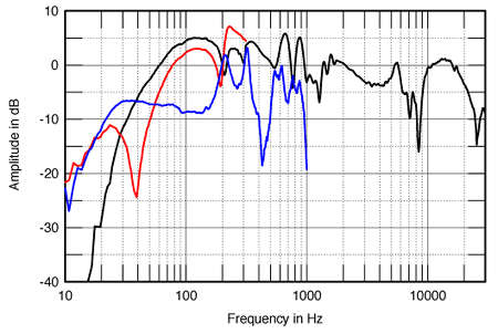
Looking at the graphs, Woofer, FR graph here: http://www.tymphany.com/datasheet/printview.php?id=230
bit of a peak at ~ 6K, xover no higher than 3K, 2nd order to avoid a notch filter?
Tweeter data here: http://www.d-s-t.com.au/data/Vifa/D26NC-15-06.pdf
Fs 1500, so perfect for 3K xover, they recommend 2nd order...
‘Swifty’ seems to be crossed over a bit lower than that, 2nd order on woofer & 3rd on tweeter; as Sreten says, a good place to start.
But, being lazy, I’d try changing the 7.5 ohm resistor for a cap ~ 8uF, just to see what it sounds like.....
cheers,
Pete McK
Thanks allot for the help
I spent today (spring break is boring) researching crossovers and what not.
I am pretty sure im going to go with a Butterworth 2nd order at 3,000hz. My only problem right now is getting the correct size inductor. I can not find .45 mh air inductors. Could i just get a .5/.55 mh and unwind and cut it a bit. How would i know if i have taken enough off? I dont have access to an inductive multimeter, but i do have access to a freq generator, osciliscope, and multiple multimeters if they would help at all.
I was thinking of buying all the parts at PE and am also curious if the 12db slope crossover board would be exactly what i need to make it a bit easier on a first timer like me.
thanks again.
ccdoggy said:
I am pretty sure im going to go with a Butterworth 2nd order at 3,000hz.
Hi,
And I'm pretty sure you have no real idea of what you are doing.
Use the Swifty c/o with 3R->2.2R and 50R->22R. You can adjust
these two to control treble level, e.g. 3R=3R and 50R=10R will
reduce treble levels, probably too much, hence the above.
Other combo's are 2.5R and 2.7 R with around 15R.
The "50R" resistor position is not too critical as long as the value
is not too low, you could just use say 15R and vary "3R" in level.
") /sreten.
/sreten.PeteMcK said:
But, being lazy, I’d try changing the 7.5 ohm resistor for a cap ~ 8uF, just to see what it sounds like.....
cheers,
Pete McK
Hi, far too bright,
/sreten.Hi,
I think that your option of going with a 2nd order filter based on a 450uH inductor is likely to work as well as the swifty xcrossover and better in the end because you are taking control of it yourself rather than hoping someone elses design will work. I would just start with the 500 - 550uH inductor and see if it works you may find you don't need to unwind it at all and you can find an alignment by vairying the capacitor.
Neither of them will work properly the swifty is designed for a different tweeter drive unit, it may be from the same manufacturer but they would need to be the same for this to work. It is supprising how much drive units from the same manufacturer vairy. Besides your tweeter looks like a semi horn loaded and the swifty tweeter is a flat radator - very slim chance of these having similar roll off characteristics.
In the end you either end up with alot of trial and error or you need some measurement equipment.
Regards,
Andrew
Thanks for the help, I figure ill just go with my 2nd order design as i couldent find any info on the swifty's tweeter and to modify the values for my tweeter.
I figure for a first project trial and error is just what happens. so allot of tweaking is in my future.
When you say "Neither of them will work properly" what do you mean, neither crossover?
I figure for a first project trial and error is just what happens. so allot of tweaking is in my future.
When you say "Neither of them will work properly" what do you mean, neither crossover?
gfiandy said:
I think that your option of going with a 2nd order filter based on
a 450uH inductor is likely to work as well as the swifty xcrossover
Andrew
Hi,
No it won't.
A textbook 3KHz 6R Butterworth (0.45mH/6.25uF) is completely wrong.
Recently I'm getting very bored with being contradicted by people.
Not a dig at you personally but do not assume that something that
does not appear to you to be a good idea is not in fact sensible.
ccdoggy said:as i couldent find any info on the swifty's tweeter and to modify the values for my tweeter.
Hi,
I've already described how to modify the "3R" and "50R" resistors
in the Swifty crossover. You can tweak these values by ear.
/sreten.sreten said:
A textbook 3KHz 6R Butterworth (0.45mH/6.25uF) is completely wrong.
Out of curiosity, why wouldent it work?
Due to the Difference in Ohms of the tweeter, swifty is 4 Ohms and the one i have is 6 Ohms, Would any other changes need to be made to any other values?
Thanks again.
Hi,
The values I suggested include compensation for 3R DCR of the
Peerless tweeter compared to the 4.5R DCR of the Vifa tweeter.
The changes to "3R" and "50R" keep the load to the other
components the same as the above values with the Peerless.
Basically around 6 ohms. i.e. 3R--3R||50R = 5.8R.
2.0R--4.5R||33R = 5.9R - I assume will be too bright.
2.2R--4.5R||22R = 5.9R
2.5R--4.5R||15R = 5.95R
2.7R--4.5R||12.5R= 6R.
3R--4.5R||10R = 6.1R. - I assume will be too dull.
Why wouldn't it work ?
Because a decent answer to that question would need a small textbook.
http://www.rjbaudio.com/Audiofiles/FRDtools.html
http://www.geocities.com/woove99/Spkrbldg/
http://www.troelsgravesen.dk/Diy_Loudspeaker_Projects.htm
http://www.humblehomemadehifi.com/
http://www.rjbaudio.com/projects.html
http://www.zaphaudio.com/
FWIW tweeter substitution with the Swifty 18dB/octave treble
section is not that problematic. Bass unit substitution is a no-no.
/sreten.
The values I suggested include compensation for 3R DCR of the
Peerless tweeter compared to the 4.5R DCR of the Vifa tweeter.
The changes to "3R" and "50R" keep the load to the other
components the same as the above values with the Peerless.
Basically around 6 ohms. i.e. 3R--3R||50R = 5.8R.
2.0R--4.5R||33R = 5.9R - I assume will be too bright.
2.2R--4.5R||22R = 5.9R
2.5R--4.5R||15R = 5.95R
2.7R--4.5R||12.5R= 6R.
3R--4.5R||10R = 6.1R. - I assume will be too dull.
Why wouldn't it work ?
Because a decent answer to that question would need a small textbook.
http://www.rjbaudio.com/Audiofiles/FRDtools.html
http://www.geocities.com/woove99/Spkrbldg/
http://www.troelsgravesen.dk/Diy_Loudspeaker_Projects.htm
http://www.humblehomemadehifi.com/
http://www.rjbaudio.com/projects.html
http://www.zaphaudio.com/
FWIW tweeter substitution with the Swifty 18dB/octave treble
section is not that problematic. Bass unit substitution is a no-no.
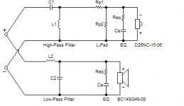
/sreten.I am trying to interpert the Swifty's crossover and figure out what it is.
So far from what i see its a 2nd order on the woofer, a 3rd order for the tweeter with a L-pad. The part i cant get is what is the two 1Resistors for?
Also for the life of me i cant figure out what the crossover point is.
After this i think ill have all the info i need. Thanks!
So far from what i see its a 2nd order on the woofer, a 3rd order for the tweeter with a L-pad. The part i cant get is what is the two 1Resistors for?
Also for the life of me i cant figure out what the crossover point is.
After this i think ill have all the info i need. Thanks!
This speaker uses the same woofer, and has a conventional 2nd order xover, probably a bit easier to follow than the 'swifty'
http://www.lonesaguaro.com/speakers/onyx/Onyx.htm
http://www.lonesaguaro.com/speakers/onyx/Onyx.htm
PeteMcK said:This speaker uses the same woofer, and has a conventional 2nd order xover, probably a bit easier to follow than the 'swifty'
http://www.lonesaguaro.com/speakers/onyx/Onyx.htm
Hi,
Easier to follow but not as good.
/sreten.P.S. - when choosing your xover parts values, you need to use the impedance of the driver at the xover frequency - not the 'nominal' impedance. If you can't measure this directly, you can read it off from the graphs I linked above.
Online calculators here: http://ccs.exl.info/calc_cr.html#second
Online calculators here: http://ccs.exl.info/calc_cr.html#second
ccdoggy said:I am trying to interpert the Swifty's crossover and figure out what it is.
So far from what i see its a 2nd order on the woofer, a 3rd order for the tweeter with a L-pad. The part i cant get is what is the two 1Resistors for?
Also for the life of me i cant figure out what the crossover point is.
After this i think ill have all the info i need. Thanks!
Hi,
The two 1R resistors are for damping. One also reduces the effects
of the variability of amplifier out impedance, the other reduces the
effects of component variation in the treble section. Both of them
reduce the maximum phase angles of the speaker impedance.
The section are 2nd and 3rd order electrical, however the acoustic
order of the crossover is not obvious, it is likely quasi 4th order
with some assymetry in the treble section to account for driver
offsets.
The Bass section has baffle step compensation which accounts
for what appears to be a too large inductor. The crossover
point is near 3Khz (from the treble section).
FWIW the Swifty uses the same drivers as the Meadowlark Swift
and the following shows what happens when you use a 1st order
electrical crossover when it is basically not suitable for the job :
http://www.stereophile.com/floorloudspeakers/104meadowlark/index.html
not what I'd call ideal .........
/sreten.Hi,
The chance of either of these crossovers working without experimentation is about zero.
Correcting the impedance of the tweeter is not going to correct the fact that the phase response and roll off will not be the same and you will most likely end up with a phase mismatch at the crossover. The vifa tweeters fs is 1.5KHz and the Peerless one is 1.1KHz. The tweeters response normally turns over at the Fs point. (unfortunately the frequency response of the Peerless is not on its data sheet). So the response of the Peerless is likely to go some 400Hz lower than the Vifa one; this meams that the acoustic response and phase will be wrong. The Peerless doesn't have its SPL listed on its data sheet. So it may be more or less sensitive than the Vifa part, my guess would be less sensitive as it has no semi horn loading which increases sensitivity.
To be fair I guess the bass driver should have been corrected for any lift or roll off in the xover region and as pointed out baffel step correction. So it may work better than starting from the theoretical electrical solution. But just adjusting for impedance is not going to fix any phase and roll off errors in the tweeter.
If you want to go with this solution by far your easiest solution would be to change the tweeter to the one used with the swifty crossover. (if it will fit in the cabinet)
Otherwise you are going to be trying to adjust a fairly complex crossover without any measurement equipment. Without measurement equipment I think you are going to spend a very long time fiddling. I guess my point was it is more inportant that you take ownership of the design and learn how it works, in the end this should alow you to get to something you want.
Regards,
Andrew
PeteMcK said:"Easier to follow but not as good"
Sreten, If you gave us the reason, we'd all be able to learn from you...
Hi,
More really my opinion than a statement of fact. Though I do not trust :
2. You can get pretty darn close with CAD software and no measurements
5. I got lucky with this design!
Vifa BC14SG49-08 & Peerless 810100 MT - One of my first designs (Full HT)
You need some measurements of the drivers to start off with.
What CAD software and methodology ?
Personally I do not like fully zobelled bass midrange units, simply
smacks to me of not really understanding crossover design.
Sometimes partial zobelling is needed but hardly ever full.
The dip at the c/o point possibly indicates not considering driver
offset or whatever ? it is not explained and neither is the amount
of BSC and the intended placement of the speaker.
The Swifty has been built by people on this forum with good reported
results. And of course there are no specs for the Onyx Peerless tweeter.
/sreten.gfiandy said:Hi,
The chance of either of these crossovers working without experimentation is about zero.
Correcting the impedance of the tweeter is not going to correct the fact that the phase response and roll off will not be the same and you will most likely end up with a phase mismatch at the crossover. The vifa tweeters fs is 1.5KHz and the Peerless one is 1.1KHz. The tweeters response normally turns over at the Fs point. (unfortunately the frequency response of the Peerless is not on its data sheet). So the response of the Peerless is likely to go some 400Hz lower than the Vifa one; this meams that the acoustic response and phase will be wrong. The Peerless doesn't have its SPL listed on its data sheet. So it may be more or less sensitive than the Vifa part, my guess would be less sensitive as it has no semi horn loading which increases sensitivity.
To be fair I guess the bass driver should have been corrected for any lift or roll off in the xover region and as pointed out baffel step correction. So it may work better than starting from the theoretical electrical solution. But just adjusting for impedance is not going to fix any phase and roll off errors in the tweeter.
If you want to go with this solution by far your easiest solution would be to change the tweeter to the one used with the swifty crossover. (if it will fit in the cabinet)
Otherwise you are going to be trying to adjust a fairly complex crossover without any measurement equipment. Without measurement equipment I think you are going to spend a very long time fiddling. I guess my point was it is more inportant that you take ownership of the design and learn how it works, in the end this should alow you to get to something you want.
Regards,
Andrew
Hi,
In your opinion and "about zero" is not a very considered one.
Whilst some of what you say it true, and some of it is not, none of
it has the catastrophic consequences you seem to be suggesting
will occur, whilst the "alternative" textbook Butterworth only on
both drivers is a walking disaster area.
Anyway we now have a data sheet for the Peerless ......
http://www.madisound.com/catalog/PDF/AC25TG05-04.pdf
So there is no excuse not to redesign the treble section of the Swifty
for the D26 in a simulator .... and show how far right or wrong I am ...
how can anyone resist ................
/sreten.You could try this one out. A good starting point, and maybe good enough to use.
Frequency: 3500 Hz
C1 = 3.9 µF,
C2 = 5 µF,
L1 = 0.56 mH,
L2 = 0.3 mH,
Tweeter
Impedance EQ
Req = 4.7 ohms
Ce = 2.2 µF
L-pad
Rp1 = 2.2 ohms
Rp2 = 22 ohms
Woofer
Impedance EQ
Req = 5.6 ohms
Ce = 20 µF
Frequency: 3500 Hz
C1 = 3.9 µF,
C2 = 5 µF,
L1 = 0.56 mH,
L2 = 0.3 mH,
Tweeter
Impedance EQ
Req = 4.7 ohms
Ce = 2.2 µF
L-pad
Rp1 = 2.2 ohms
Rp2 = 22 ohms
Woofer
Impedance EQ
Req = 5.6 ohms
Ce = 20 µF
Attachments
- Status
- This old topic is closed. If you want to reopen this topic, contact a moderator using the "Report Post" button.
- Home
- Loudspeakers
- Multi-Way
- Replace crossover in existing box