If I double C23's value? What frequencies are we talking about? KHz?
It doesn't quite work like that I'm afraid. The zobel network terminates the amplifier output at hf and ideally makes the reactive part of a speaker load (its impedance) look basically resistive.
With the greatest of respect, you are never going to fix this approaching the problem this way. You need to set out a definite plan to follow, to test and build up the amplifier in stages and be prepared for some disappointments on the way. Just thinking you can change the value of some parts or throwing more new FET's at this isn't the way to go. That point has been and gone, the past history of the amp has proved that. Also, when there is doubt over stability and so on, then an oscilloscope becomes an essential tool. It helps confirm all is well and shows problems even when basic DC checks appear OK.
I just wonder if this is do-able, given the equipment you have and your experience. Just trying to be realistic, but, if you want to try then we can come up with a plan to follow
")
Thank you for the guidance, I know where I am standing, I know this is a hard case especially for a rookie. The problem is that my financials are quite bad so sending the amp to the UK is a bit ..painful. I also asked help from local technicians but they didn't want undertake this. There is also the local dealership but the amp has already been there once (when it failed on first week of purchase) and there was no permanent fix. So my only chance before throwing it away was to try the fix myself. Another option would be replacing the whole board but during my communication with Creek (I asked for a price twice) there was no answer on this and I also assume that the price will not be cheap for a device of this class. And it doesn't seem that I will be able to buy a similar amp in the future. If it had many miles on the clock, I would retire it more easy. But it is a brand new expensive device.
I don't the full history of this, but you say the amp was only a week old when it failed ! So you bought it new... you mention it being brand new ?
Once you've worked on it all your consumer rights will go out of the window... so maybe I am misunderstanding you.
Only you know what you want to do and what you feel able to do... but... if you want to have a go at fixing this we can have a go via the forum but its going to be an uphill struggle. Have you anything to lose though... the amp is not saleable as it is, and having been worked on the manufacturer won't accept liability.
Its your call
I don't the full history of this, but you say the amp was only a week old when it failed ! So you bought it new... you mention it being brand new ?
Once you've worked on it all your consumer rights will go out of the window... so maybe I am misunderstanding you.
if you read my first post, I tried to clarify the full story but i am not speaking my native language here so perhaps i failed to be clear.
the amp was bought brand new on 2010. it failed on first week and repaired by the dealer on warranty. the second failure happened weeks ago, but these four years i haven't used the amp more than 15 or 20 hours, so its out of warranty, when i said its brand new i meant it has played very few hours.
Which have you changed and were all four faulty ? The diagram shows all four to be the same type.
delayed answer, on the "bad" channel they all were faulty. When the "good" channel failed, only Q15 and Q18 burned.
I was working today on the same amp that had a bit of buzz in the left channel. I was swapping the signal input cables to locate the problem and managed to plug in the R signal cable in IDLE connector JP104 (assume that is the bias measurement spot). Instantly after power up I had smoke from the area where the JP104 is and both R channel 10A PSU fuses died. After replacing the fuses R channel is dead. Can anyone point me in the right direction in fault finding while I am settling down and dealing with my range and stupidity.
I did measure output devices (soldered) they do not show any signs of shorts - both source to gate and source to drain pass a MM diode test - identical on both channels.
The signal device at the time was an mp3player with output R=2 ohm C=174uF and L=146uH measured with an LCR meter @1KHz. So essentially a short.
Last edited:
If it was the bias test point that you connected to an input cable then you may well have shorted the positive rail to ground via the low value 0.33 ohm sensing resistor that is in series with the output devices. There is a similar resistor on the negative rail too but with no test point access to it. If that is what happened then the resistors will have failed. If not then you have an uphill struggle as you would have to identify on the circuit exactly what this plus connected to and shorted out.
Doing just that shouldn't cause any problem as its really just shorting the 0.33 ohm out. I think what you have done is fed the 40 volts down whatever you plugged in there and fed it back to an earlier part of the circuit. Did the MP3 leads connect to the other channel as well at the same time this happened. If so you have a "loop" current could flow around and then find its way back to the amp via that route.
I would need one in front of me and to actually see what you had done in order to be able to tell. If smoke came out then you should be able to find some physical evidence somewhere, blackening of a part, small transistors often subtly "split" but you have to look closely. And smell the board. The area of the mishap should be traceable. If its not then you have to find the problems via normal fault-finding techniques and checking DC conditions and so on.
I would need one in front of me and to actually see what you had done in order to be able to tell. If smoke came out then you should be able to find some physical evidence somewhere, blackening of a part, small transistors often subtly "split" but you have to look closely. And smell the board. The area of the mishap should be traceable. If its not then you have to find the problems via normal fault-finding techniques and checking DC conditions and so on.
What is the chance that I did damage the output devices? Was there any consensus on the suitable replacements?
Yes I had both channels connected - now the other channel still works fine. I was looking for the burn marks and smelling but could not detect anything - a little bit of smoke came out. I did check most of the transistors and they seam to be fine - will try that IRF9610 next.
Yes I had both channels connected - now the other channel still works fine. I was looking for the burn marks and smelling but could not detect anything - a little bit of smoke came out. I did check most of the transistors and they seam to be fine - will try that IRF9610 next.
Last edited:
It looks that the problem could be in the signal input side - I measure 100Kohm resistance at the L side and a short at the R side without having input cables plugged in the main amp board or having anything plugged in the amp. Both input relay coils measure correct resistance. Not sure if the other input circuit is for the balanced only or RCAs as well
I've no quick answers or fixes I'm afraid. You are going to have to start with the basics... check the rails are correct, check the output DC voltage is essentially zero (no offset) and that the output stage is passing the correct current (measured across the 0.33 ohm... compare it to the other channel, don't alter any presets).
Those tests will show up any failed output devices.
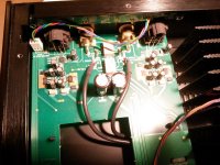
If you can measure this huge descrepency between left and right inputs then that is perhaps the place to start with some basic checks and tests. I can see what looks like an opamp on there and what could be some discrete regulators of some sort.
Those tests will show up any failed output devices.
If you can measure this huge descrepency between left and right inputs then that is perhaps the place to start with some basic checks and tests. I can see what looks like an opamp on there and what could be some discrete regulators of some sort.
Just confirmed that both output stages are 100% fine. Readjusted idle current a bit but there was no damage to them. However, only L channel input is functional - the R one remains shorted (hence no sound at the aftermath test - sorry for being hasty). I tested the channels by using the L input only and plugging it in each output stage at a time.
It is getting late here - I will have to continue tomorrow.
It is getting late here - I will have to continue tomorrow.
- Home
- Amplifiers
- Solid State
- Repair help needed - Creek Destiny