Keep the amplifier well ventilated at all times, make sure that mains voltage in your area of operation complies with the amplifier
Other than that you should consider a visual inspection of the soldering since it is known that there is a number of soldering issues in specific areas of this amplifier as described some posts ago .
As we speak i am working with a similar amplifier a cousin of the Creek with similar issues that likes to blow the LTP due to a considerable amount of bias , since smd transistors cannot dissipate the heat i am moving to standard TO 92 types of the same specks to see how far i will go with that . I expect that if one manages to replace more parts from smd to normal will improve the problem .
It could be a nice option for the Creek also
Please notice :
Well ventilated means to make sure that nothing is above the amplifier forced cooling with a ventilator will probably solve the thermal stress of the pcb but will create a million other problems
Forced cooling with a ventilator could be done for the output stage only but it doesnt need it so this is a dead end .
Kind regards
Sakis
Last edited:
Hello again..... a year later I decided to use my amp again (the AV receiver has the master entertaining role in my living room playing kids' music & movies..)
Well guess what.. it failed once more.. DC heard on the speakers, protection came on and here we are again.
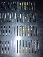
To remind you the case, my amp kept burning the output transistors since new. The manufacturer sent me another refurbished final stage board since repairing mine was not possible. It worked ok for a while but the new board failed too. I don't know if it is worth or not to spend more time (or money) on this.
Well guess what.. it failed once more.. DC heard on the speakers, protection came on and here we are again.
To remind you the case, my amp kept burning the output transistors since new. The manufacturer sent me another refurbished final stage board since repairing mine was not possible. It worked ok for a while but the new board failed too. I don't know if it is worth or not to spend more time (or money) on this.
I cannot say it is a cause of anything in particular but you have left the amplifier unused for long periods before some major failures occurred. Perhaps the failures also occurred after heat had accumulated in the amplifier after some period of operation - maybe in warm weather? These possibilities may be doubtful and very difficult to check but there are not many alternatives left to consider either.
Rather than waste more time and wind up with the same poor results as before, why not talk to or visit Sakis?
Rather than waste more time and wind up with the same poor results as before, why not talk to or visit Sakis?
Last edited:
Given the amps history, the fact it failed when new, the fact that a manufacturer replacement board has also now failed would all seem to suggest that the product is a dud unfortunately.
Given that this was a supposedly prestige product then I think I would be taking this up with the manufacturer and looking for answers.
Probably not what you want to hear but you have to be realistic. If it is in good cosmetic condition then perhaps consider selling it for spares or repair.
Given that this was a supposedly prestige product then I think I would be taking this up with the manufacturer and looking for answers.
Probably not what you want to hear but you have to be realistic. If it is in good cosmetic condition then perhaps consider selling it for spares or repair.

This is an English speaking forum. If you wish to post in another language, post it also in English.
Google translate:
To jest forum anglojęzyczne. Jeśli chcesz publikować w innym języku, opublikuj go również w języku angielskim.
Dziękuję Ci.
Google translate:
Hello everyone, I need a schematic for creek destiny amplifier, I will be grateful for any help
Thank you.
Hi All,been looking at this and i have been very skeptic about and since now i have more experience about the specific amplifier here is a few things :
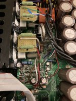
--The specific amp has a horrible thermal design IE : even though the amplifier area is well designed and cooling is efficient enough unless you stay in Sahara the rest of the amplifier has plenty of thermal issues .
--Filter capacitors next to 15V zener in both ch . have been found to be an open circuit no capacitance on them at all C29-30-129-130
--Likewise filter capacitors next U505-506 was also blown to Jupiter
--In secondary power supply C233-234 presented quite high ESR eventhough capacitance appeared to be with in normal levels ...
--In some versions there is soldering issues down under the secondary transformer especially the one that is brownish color ( Factory tip )
--In most of them there was soldering issues as you look the amplifier from the front and exactly on the edge of the board where it meets the face plate exactly left from the HP plug the all area suffers from soldering issues Q9-11-7 and so on including most of the resistors which is also a factory tip since it seems that the robot was kinda lazy there .
--Most impressive was that decoupling capacitors on both servo amplifiers U1 and U101 was actually boiling hot but this was the weirdest of them all since these are small film SMD and DNC capacitors (DNC = Do Nothing Capacitors ) and their job is to decouple the 15+15 rails ( second opinion here might do some help ) .
--Finally the real failure was the servo amplifier but not as part but mostly as soldering Good reflow there started the amp without problems ....
Summary of the above is that this is a Chinese made amp , I dont thing that much can be done to improve the "thermals " there and actually i dont see your amplifier starting unless you make sure that the problems i traced are solved and probably some others that haven't appeared yet in the amplifier i repaired .
Its a pity since this amp actually sounds very fine , unique output stage and also way too young to suffer from a high number of problems where the 99% of them is thermal alike most UK designed amplifiers in the past ( I expect now days that are China produced that the Chinese second thought the designers on this .... )
Kind regards
Sakis
I ran across many of the above in repairing the Destiny. I've replaced nearly all the components on the amp board, the majority were out of preventative maintenance and my learning curve
") . All electrolytic caps are Nichicon or Panasonic rated for 105C at a few thousand hours w/ low ESR. I borrowed a IR laser guided thermometer (not the best tool and I imagine these components are small WRT to the sensor area) and measured the U1 and U2 power supply caps Sakis pointed out. Temperatures do seem rather hot after running the amp for an hour: C29 and C30 (SMD electrolytic) up to 75C. And C19,C20,C33,C44 (MLCC) up to 80C. Is there cause for concern at these temperatures? I'm wondering if searching for lower ESR and higher voltage rated caps would improve conditions, but I am stuck with a small footprint. Or are these thermal issues design flaws that should be checked on every few years? Fortunately these SMD caps are easy and cheap to replace. Any help is appreciated. FWIW The output device heatsinks are a gentle 40C so that seems to be working ideally.
. All electrolytic caps are Nichicon or Panasonic rated for 105C at a few thousand hours w/ low ESR. I borrowed a IR laser guided thermometer (not the best tool and I imagine these components are small WRT to the sensor area) and measured the U1 and U2 power supply caps Sakis pointed out. Temperatures do seem rather hot after running the amp for an hour: C29 and C30 (SMD electrolytic) up to 75C. And C19,C20,C33,C44 (MLCC) up to 80C. Is there cause for concern at these temperatures? I'm wondering if searching for lower ESR and higher voltage rated caps would improve conditions, but I am stuck with a small footprint. Or are these thermal issues design flaws that should be checked on every few years? Fortunately these SMD caps are easy and cheap to replace. Any help is appreciated. FWIW The output device heatsinks are a gentle 40C so that seems to be working ideally.Kind Regards,
Gregory
Last edited:
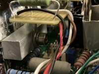
FWIW I've improved the thermal management of the Creek Destiny's power amp section by removing 4 x 2k2 (SMD) resistors ( 2 in the PSU for DC servo, and 2 in main amp section) for each channel, and mounting THT resistors just below the main heatsink heating vents. These SMD chip resistors run around 80C, and cause excessive heat in the PCB which then conducts through nearby components. Each resistor dissipates 0.65Watts of heat, thats about 3 Watts per channel heating the PCB in a small area (square inch?). I would recommend this DIY mod (compliments to nattawa)Hi All,
I ran across many of the above in repairing the Destiny. I've replaced nearly all the components on the amp board, the majority were out of preventative maintenance and my learning curve
Kind Regards,
Gregory
to anyone who wants to do some preventative maintenance on the amp sections.$20 in parts and 6 hours of work. The hardest part is routing, cutting the wires to length and soldering them to the SMD pads. The PCB is much cooler at around 50-60C. Also the DC offset is more stable - there were inexplicable ~5mV DC offset spikes apparently caused by this heat issue. The 3mm thick aluminum lid above the resistors is a tad warmer but still not too hot to the touch.
Attachments
Last edited:
- Home
- Amplifiers
- Solid State
- Repair help needed - Creek Destiny