Additionally another relay + resistors could be added then to increase the resolution of the stepped attanuator to may be 0.5 db (128 steps).
There are obviously many opinions but have you tried your 1 dB step in practical use and still think you need smaller steps? I was even thinking of ditching the 1 dB relay in my own version but still decided to keep it. I am now laying out my board, should probably finish next weekend. It will be a 15x10cm board with 2 balanced inputs and balanced outputs on-board and wiring options for third input (balanced or unbalanced) and unbalanced outputs. Arduino-compatible microcontroller circuit with some breakout connectors will be on-board as well.
Speaking of volume steps, I measured my OnePlus 3 phone's audio output steps as I find them too coarse in my preferred range. I found the steps to be as large as 5 dB in the middle of the range (what I usually use as I do not listen to very loud) and 2 dB at the louder end.
You can change the step dB value by changing the resistor values...................... Additionally another relay + resistors could be added then to increase the resolution of the stepped attanuator to may be 0.5 db (128 steps).
Just my thoughts (and suggestions)")
If have 64 steps and each one is 1dB, then you have a range of 64dB
If you want 0.75dB per step, then you get a range of 48dB
If you want 0.5dB per step, then you get a range of 32dB
It is completely within the choice of the Builder.
I asked this on the latest BPBP GB too...
Anyone have an idea how to mount the VoICB board from Hans P. ?
It doesn't have mounting holes, thus chassis mounting seems not to be possible especially because of its rather "compact" dimensions.
Because of those Hypex regulators "overlapping" on the left using dual row "very long" pinstrip headers (>30 mm, dual insulator) soldered in place of the 10 kOhm pot, as suggested, might be possible, but will restrict access to those BPBP components directly underneath it, which I don't like. Note: The VoICB is then sitting "on top" of the BPBP. Otherwise one has to unsolder the VoICB before getting at those components and locations located underneath it. Height might be problematic too...
Any 90° mounting done without those Hypex regulators getting into its way either ?
This way the VoICB would sit right in front of the BPBP (vertical orientation) centered in front of the 10 K pot location.
What available hardware / connectors did you use for this ?
I tried a 90° dual row pinstrip header (pot location) for this already but it doesn't fit (to short) having the VoICB conflicting with those Hypex regulators on the left (again).
May be any pictures available if done so ?
Attachments
Last edited:
I bought the Maya controller with your VoICB stepped attenuator board from vicol-audio.
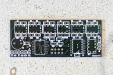
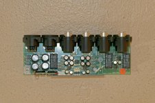
I admire the layout of that densly packed PCB but after a closere look have two "wishes" for a board version 2.0, if there ever will be one:
1) the placement of those direct "pot replacement connections" (6+2) is unfortunate, because the Hypex regulators are in the way making it necessary to have the PCB rising quite high above the BPBP board overlapping one of the Hypex regulators. If that connection would have been placed somewhat further left the VoICB would have fitted snuggly just above the small electrolyte capacitors and relays etc.
2) extending the PCB even further right would allow added mechanical support (and direct connection) to that input toggle switch connections underneath. Additionally another relay + resistors could be added then to increase the resolution of the stepped attanuator to may be 0.5 db (128 steps).
Just my thoughts (and suggestions)
Thanks for the suggestions.
1) I mounted the volCB with an angled board to board connector, soldered on both sides.
And since the Vol board is very light, no further support was needed with this firm connection.
In this case the VolCB is standing vertically before the BPBP board.

2) The JND (just noticeable difference) lies at ca. 0.7dB, so having 0.5dB volume steps does not make much sense.
Therefore 1dB steps is as low as you should go.
Hans
Hi Hans,
thanks for the prompt response.
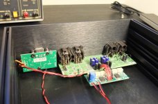
Refering to that suggestion of mounting the VoICB I tried exactly what you suggested, but with seemingly different results.
I doesn't work in my case because the 90° pinstrip header I got and which seems to be the only size (length) available is just to short (I couldn't find any longer ones on the internet looking at the database of several major suppliers).
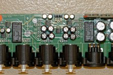
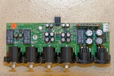
In my situation using the method and part(s) you described the VoICB (almost ?) touches one of the Hypex regulators (right one - 2nd picture), especially if you realize, that the through-hole parts like the relays haven't even been installed yet, which should complicate the situation even further.
To illustrate it, I made several photos of the situation (attached).
Just wondering what you have done differently...
PS.: Any parts reference for your connector ?
thanks for the prompt response.
Refering to that suggestion of mounting the VoICB I tried exactly what you suggested, but with seemingly different results.
I doesn't work in my case because the 90° pinstrip header I got and which seems to be the only size (length) available is just to short (I couldn't find any longer ones on the internet looking at the database of several major suppliers).
In my situation using the method and part(s) you described the VoICB (almost ?) touches one of the Hypex regulators (right one - 2nd picture), especially if you realize, that the through-hole parts like the relays haven't even been installed yet, which should complicate the situation even further.
To illustrate it, I made several photos of the situation (attached).
Just wondering what you have done differently...
PS.: Any parts reference for your connector ?
Attachments
Last edited:
Hi Hans,
thanks for the prompt response.
Refering to that suggestion of mounting the VoICB I tried exactly what you suggested, but with seemingly different results.
I doesn't work in my case because the 90° pinstrip header I got and which seems to be the only size (length) available is just to short (I couldn't find any longer ones on the internet looking at the database of several major suppliers).
In my situation using the method and part(s) you described the VoICB (almost ?) touches one of the Hypex regulators (right one - 2nd picture), especially if you realize, that the through-hole parts like the relays haven't even been installed yet, which should complicate the situation even further.
To illustrate it, I made several photos of the situation (attached).
Just wondering what you have done differently...
PS.: Any parts reference for your connector ?
Instead of mounting the Hypex regulator under 90 degrees on the BPBP, it can be mounted leaning quite a bit backwards, giving more than enough room for the VolCB.
I think you used a correct angled header, but longer versions are also available, the Samtec HTSW-103-25-G-D-RA, available from Farnell.
Hans
Already found issue with LCD printing volume /gain :
Here the version with bug corrected , please test this on.
Seems to work fine. I appreciate your efforts to improve your software.
Hi all ,
please see the new version of firmware 1.3.h for BPBP Maya:
-> maya_v_1_3_h_lcd_bpp_ninp = for lcd version
-> maya_v_1_3_h_rays_oled_bpp_ninp = for oled version
that resolve some bug related to the user that can edit more input number than actual number exists and also the oled version have the new power off oled after 1 minute of inactivity like the Maya oled new version.
Please test and feedback .
Attachments
Instead of mounting the Hypex regulator under 90 degrees on the BPBP, it can be mounted leaning quite a bit backwards, giving more than enough room for the VolCB.
I think you used a correct angled header, but longer versions are also available, the Samtec HTSW-103-25-G-D-RA, available from Farnell.
Hans
Unfortunately I dont have an account with Farnell and Mouser doesn't offer it. But I checked the German supplier Reichelt (www.reichelt.com) and they are offering something similar which I ordered right away including a matching femal header too.
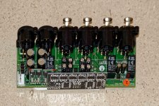
Today I got the package and it fits. Two variants can be constructed this way:
- soldering it to both boards (BPBP, VoICB) using just the male header
- soldering it to the BPBP using the male header and soldering a female header to the other side (VoICB), making it removable this way and extending it by about 2.5 mm further out.
The part numbers are:
- male, 2 row, 3 pins each: MPE 088-2-006, price: ~0.17 EUR
- female, 2 row, for 3 pins each: MPE 094-2-006, price: ~0.24 EUR
The matching pin length is about 8.x mm. This provides enough clearance for the Hypex regulators and holds the VoICB firmly attached.
Hi all ,
please see the new version of firmware 1.3.h for BPBP Maya:
-> maya_v_1_3_h_lcd_bpp_ninp = for lcd version
-> maya_v_1_3_h_rays_oled_bpp_ninp = for oled version
that resolve some bug related to the user that can edit more input number than actual number exists and also the oled version have the new power off oled after 1 minute of inactivity like the Maya oled new version.
Please test and feedback .
I tried the OLED version out. Upgrade went ok, but following observations
* When I go to 'number of input' and enter that menu, then the rotary encoder will not change the number of inputs. I did discover that the vol+/- on remote did work and Mute on remote saved and exited that menu. Is this by design?
* 'the real gain' menu - I'm pretty sure that when I entered the menu first time I could only choose gains between 10...70 and I could not select 0. I chose 10 and then saved and exited. When I went in second time I could also choose 0... so might be a small bug there with range/initial value.
Anyhow, now I have 2 inputs and max gain of 0 as I need, so happy and will test further.
Thanks for the effort to add these new settings!
Last edited:
Unfortunately I dont have an account with Farnell and Mouser doesn't offer it. But I checked the German supplier Reichelt (www.reichelt.com) and they are offering something similar which I ordered right away including a matching femal header too.
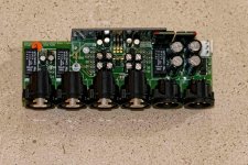
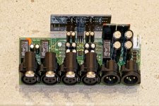
Today I got the package and it fits. Two variants can be constructed this way:
- soldering it to both boards (BPBP, VoICB) using just the male header
- soldering it to the BPBP using the male header and soldering a female header to the other side (VoICB), making it removable this way and extending it by about 2.5 mm further out.
The part numbers are:
- male, 2 row, 3 pins each: MPE 088-2-006, price: ~0.17 EUR
- female, 2 row, for 3 pins each: MPE 094-2-006, price: ~0.24 EUR
The matching pin length is about 8.x mm. This provides enough clearance for the Hypex regulators and holds the VoICB firmly attached.
Attached you will find some photos about what I described above:
Attachments
I tried the OLED version out. Upgrade went ok, but following observations
* When I go to 'number of input' and enter that menu, then the rotary encoder will not change the number of inputs. I did discover that the vol+/- on remote did work and Mute on remote saved and exited that menu. Is this by design?
* 'the real gain' menu - I'm pretty sure that when I entered the menu first time I could only choose gains between 10...70 and I could not select 0. I chose 10 and then saved and exited. When I went in second time I could also choose 0... so might be a small bug there with range/initial value.
Anyhow, now I have 2 inputs and max gain of 0 as I need, so happy and will test further.
Thanks for the effort to add these new settings!
Yes, by design only remote vol +/- can change value in the sub menu în settings.
For second will be 0... 100 will check code for this Bug.
I "need" to add unbalanced RCA inputs and outputs for this to be compatible with my old design. What is your opinion on how to connect the unbalanced input?
You could replace your interconnects and leave the inputs all balanced.
RCA connector - balanced/twisted cable - XLR connector
This is what I'd be inclined to do
You could replace your interconnects and leave the inputs all balanced.
RCA connector - balanced/twisted cable - XLR connector
This is what I'd be inclined to do
Yes, that is what I am doing. I will have 2 XLR inputs and XLR outputs fitted on the 15x10cm PCB and options for another input, XLR or RCA, and RCA outputs to be wired to panel-mounted connectors.
I needed to change my layout when it was almost ready but should be finished with it this weekend. 4 layers would be nice when having the microcontroller circuit as well but will fit it in 2. 4 layers become quite expensive after 10x10cm. Expect updates and performance measurements at the end of May. The first board will be the preamp in my PSU - DAC - PRE - AMP headphone setup.
Hello,
I've tried almost every IR remote control in the house but Maya wasn't able to recognize any. During this ir remote testing I accidently manage to enable temperature function and now I can't turn it off so the only way to change input or volume is by blutooth which works but encoder doesn't work at all now and annoying message for high temperature overload is there all the time. How to reset this behavior and why Maya can't recognize any of the remotes in the first place? Oh, and can we have level displayed from -57dB to +6dB?
I've tried almost every IR remote control in the house but Maya wasn't able to recognize any. During this ir remote testing I accidently manage to enable temperature function and now I can't turn it off so the only way to change input or volume is by blutooth which works but encoder doesn't work at all now and annoying message for high temperature overload is there all the time
. How to reset this behavior and why Maya can't recognize any of the remotes in the first place? Oh, and can we have level displayed from -57dB to +6dB?Hello,
I've tried almost every IR remote control in the house but Maya wasn't able to recognize any. During this ir remote testing I accidently manage to enable temperature function and now I can't turn it off so the only way to change input or volume is by blutooth which works but encoder doesn't work at all now and annoying message for high temperature overload is there all the time
Hi,
Maya is able to detect two infrared remote protocols, RC5 and NEC. Your remote will not be detected if make use of Samsung, Sanyo, RC6 etc.
By default Maya come set for NEC, so if you have an Apple remote this will work right away.
Before set a new remote go to "Settings menu" --> "IR remote type" and select "RC5 Philips"
Specific remotes you may use:
For RC5 protocol -> Naim, Marantz, Philips - audio etc.
For NEC -> Apple and NEC
Please note that to edit menus, you need to set a compatible RC5 infrated remote.
To deactivate temperature go to "Settings menu" -->> "Settings" --> "Ena/dis temp sh" rotate encoder and select "nosh temperature" than exit settings.
Regards,
Tibi
Well, this is the problem because I can't see anything but this overheat temperature message on the display. Rotating encoder doesn't work. Only power button works
. I think the only solution to see anything but this message is to connect temp probes (which I don't have) to get it out off temperature error state. Which temperature probe chip did you use on breakout boards?Also, I'm preparing Raspberry PI as AVR programmer. Maybe reflashing would help.
Flashing Maya with Raspberry pi went smooth and now need to find rc5 type remote.
If anyone else want to try just follow instructions from https://learn.adafruit.com/program-an-avr-or-arduino-using-raspberry-pi-gpio-pins/overview
If anyone else want to try just follow instructions from https://learn.adafruit.com/program-an-avr-or-arduino-using-raspberry-pi-gpio-pins/overview
Last edited:
- Status
- This old topic is closed. If you want to reopen this topic, contact a moderator using the "Report Post" button.
- Home
- Source & Line
- Analog Line Level
- Remote Control for the BPBP