Please someone Im going mad!! work done:
checked dc off was at 50 mv - should be ok?
relay works fine tested with 12v clicks
there is 40v ish at the diode by relay.
Resoldered all connections
But relay is still not clicking on. I dont understand there is a high voltage there already!? Any help appreciated
also checked audio beofre relay was fine. Relay is HLS-4453(18F)
from ground to diode is 42v on either pin
Attachments

Last edited:

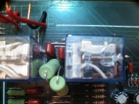
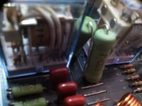
Are those large green resistors in series with the relay coils ? If so then it could be normal to see a high voltage on the coil. Its a standard technique.
Edit... or the coils could be in series.
If you have 42 volts on both sides of the coil then the reason the relay isn't activated is simply because it is not being told to turn on.
Edit... or the coils could be in series.
If you have 42 volts on both sides of the coil then the reason the relay isn't activated is simply because it is not being told to turn on.
Last sentence should have read (missed the word not out)
If you have 42 volts on both sides of the coil then the reason the relay isn't activated is simply because it is not being told to turn on.
Hi Mooly, I have attached pictures of resistors. I dont understand when I connected 12v it clicked! but at 42v no? And I think it attaced in series
Attachments
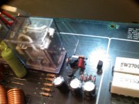
If you measure the voltage to the relay coil from ground then I think you will find 42 volts on both sides. That means no voltage across the relay. In other the words the diode will have 42 volts on both sides.
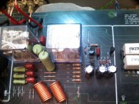
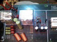
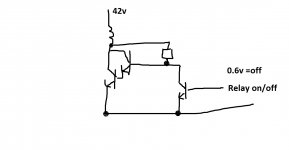
It looks like the coil goes to those two transistors, and those transistors are configured to make a high gain 'darlington' configuration. From there it is impossible to know without a circuit diagram what triggers the relays and what the conditions should be.
It looks like the coil goes to those two transistors, and those transistors are configured to make a high gain 'darlington' configuration. From there it is impossible to know without a circuit diagram what triggers the relays and what the conditions should be.
You need to be concerned about the difference in voltage between both sides of the coil, not the actual voltage present. If you have 42V present on both sides of the, the applied voltage to the coil is 0V, so nothing happens. If you have 150V on both sides of the coil, again nothing happens. If you have 42V on one side of the coil, and 30V on the other, then things will happen.
Your switching circuit isn't working, look there instead.
Your switching circuit isn't working, look there instead.
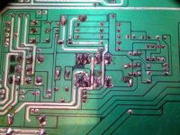
Its not easy deducing stuff from pictures but lets see what this shows.
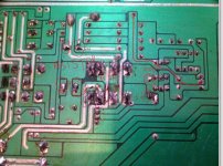
Do you have around 0.65 volts here on this print.
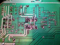
I got 0.06 Milli volts! not 0.6 volts but yes you are right thats the only thing that seems to be leading off somewhere else!
I foolowed the route of the track and it goes up and spilts in tho the different sections the surround and L and R channels. It seems into go into trasnsitors and other network of components. I'm guessing this is the signal part!? And I thought relay was just power and go! Not really!!
The relay will be powered by a DC offset detection circuit and will usually have a time delay circuit which will delay the engagement to mute power up noises from the amplifier.
There doesn't seem to be a schematic easily available for this amplifier. It's tough to figure out the circuit from pictures of the board. Mooly likely has the schematic of the drive portion correct. If you could expand on the schematic to give us an idea how the control circuit operates, we could likely point you where to look.
There doesn't seem to be a schematic easily available for this amplifier. It's tough to figure out the circuit from pictures of the board. Mooly likely has the schematic of the drive portion correct. If you could expand on the schematic to give us an idea how the control circuit operates, we could likely point you where to look.
- Status
- This old topic is closed. If you want to reopen this topic, contact a moderator using the "Report Post" button.
- Home
- Amplifiers
- Solid State
- Relay not working. Not trans or dc issue