Normally DC offset detection won't activate until over 1VDC on the output.
There are a couple different ways these circuits can operate. Some use detector ICs, some use discrete transistors and a RC network to add the on delay. Some use a detector circuit and a microcontroller. Once we figure out what yours is using we can point you where to look. It may be something as simple as a low voltage supply not powering up.
There are a couple different ways these circuits can operate. Some use detector ICs, some use discrete transistors and a RC network to add the on delay. Some use a detector circuit and a microcontroller. Once we figure out what yours is using we can point you where to look. It may be something as simple as a low voltage supply not powering up.
Normally DC offset detection won't activate until over 1VDC on the output.
There are a couple different ways these circuits can operate. Some use detector ICs, some use discrete transistors and a RC network to add the on delay. Some use a detector circuit and a microcontroller. Once we figure out what yours is using we can point you where to look. It may be something as simple as a low voltage supply not powering up.
Hi I did check all the voltages on the board and they seem fine. We are both scratching our heads to what on gods green earth is going on!
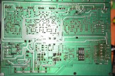
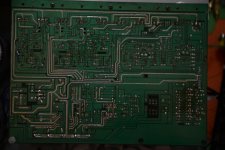
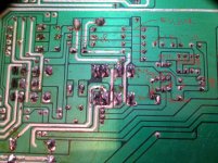
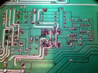
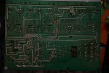
The last pic I have followed the track and marked where it has jumpers across to next tracks
Attachments


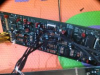
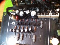
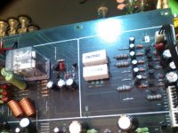
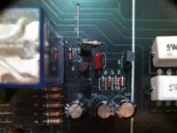
Also has massive side circuit!! And more pics of the relay side and power out to sode board. Those are the only cables coming off the main board
Attachments

Here's as much as I can figure out from the pictures. I can't tell base, emitter, pnp, npn, ect of the transistors because I can't see any part numbers. If you can add the rest we can figure out how the switching portion operates and figure out why it's not working. It doesn't have to be pretty, but we need to know how everything is connected.
Attachments
I've got most of the circuit figured out. I've written the operation of the parts on the picture. The text is pretty small.
The transistor with the ??? beside it looks like an external control input to the circuit. Is that a pnp or npn transistor?
If you power up the amplifier, voltage should slowly build up between the base and emitter of the switcher driver until it reaches ~ 0.6V. Is that happening?
Edit. The ??? is where the DC detection circuit controls the relay circuit.
Attachments

Last edited:
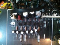
I need to draw a proper schematic and stare at it for a bit to figure out operation better, but I think there should be an external voltage source to the base of the transistor where I have the question marks. There's a jumper above the 5 resistors from the amp outputs. Where does that go to? Is it possibly a dead voltage source?

Here's what I've got figured out for the circuit operation.
That jumper likely works it's way up to the positive rail feed at the output transistors through a resistor. Are all those lines you've drawn off the main trace resistors? Does one of them go to the positive rail voltage? Is one of them open circuit?
That jumper likely works it's way up to the positive rail feed at the output transistors through a resistor. Are all those lines you've drawn off the main trace resistors? Does one of them go to the positive rail voltage? Is one of them open circuit?
Attachments
R6 7 8 9 10 are for L R C SR SL I believe makes sense! and R11 as seen in pic is for relay?
Voltage from speaker ground to R11 is = 42v from relay side and 0v on the other side!
I checked colour online it say 1m (Brown, Black,Green,Gold)
No the trace are jumpers going tino transitors directly mostly
Voltage from speaker ground to R11 is = 42v from relay side and 0v on the other side!
I checked colour online it say 1m (Brown, Black,Green,Gold)
No the trace are jumpers going tino transitors directly mostly
Attachments

- Status
- This old topic is closed. If you want to reopen this topic, contact a moderator using the "Report Post" button.
- Home
- Amplifiers
- Solid State
- Relay not working. Not trans or dc issue