Hmm... this looks like an interesting project. I've tried a couple of times to come up with a reasonable relay and resistor-network based volume control, but I've never been satisfied with the results since I've always been after a true logarithmic curve, or something very close. I really want to have consistent steps in volume from one end of the scale to the other, and I've always been super-annoyed by volume controls that couldn't get that "in-between" setting, so fine steps are important to me. Otherwise, one position is just a bit too quiet, and the next is just a bit too loud.  Combined with the prohibitive cost of relays, and the crappy log approximations one could botain with such networks, I've been increasingly drawn towards devices like the PGA2310. But, a group order could be just the thing to bring the project to maturity at an affordable price.
I think you've got the right idea to separate the microcontroller from the attenuators, as some people may want to do their own microcontroller or integrate the code into a controller doing other things as well (like me for instance), and/or put the micro in a separate chassis. But, I'm puzzled why you decided to put four banks on one attenuator board. Why not do 2 banks per board? Then you can use a single board for either one balanced channel, or a stereo pair...
Next, can I suggest something simpler than I2C for the interface? If I2C is used, then it would have to be a proper (read: meets the spec) implementation so that someone who connects these to an I2C bus with other devices on it can still use the boards. But, a proper I2C implementation would require a micro right on the attenuator PCB, which isn't an optimal solution, since the purpose of a separate micro is to get it and it's noise away from the analogue signals. I would use simple SIPO shift registers to control the relays. This would only require a 2-wire interface, and can be bit-bashed and operate at whatever frequency you want, unlike I2C which is fixed at 100 or 400kHz. Since relays are so slow to react to a change in drive signal, you can easily shift in the entire control binary value for many channels before the relays have any chance to react. Plus, you can daisy-chain as many SIPO shift reg's as you want, so your total number of channels is almost unlimited...
Jordan: the shunt method works like this: you basically have a fixed series resistor connecting to an array of switched resistors to ground (the "shunt" elements). With all the resistors turned off, your attenuation is zero, and as you shunt more resistors to ground, the attenuation increases. The shunt method reduces sensetivity to non-ideal characteristics of the shunt devices. I believe the most recent incarnation of attenuator at Pass Labs is actually using FETs as shunt switches... Which brings me to another point: FETs are way cheaper than relays, which makes it affordable to use more switched elements, thus acheiving greater precision. Drive requirements are simple too, since they can typically be turned on directly with logic-level signals, so theres another cost savings (a relay requires a drive transistor and a diode to prevent switch-off voltage spikes from destroying the transistor). It would take a bit of work to figure out the optimal arrangement, but I'm sure an arrangment of vaious combinations of parallel shunt elements could be found which gives pretty precise 0.5dB steps... not necessarily a binary progression, but more precise, and following a true log curve, thus requiring more shunt elements than a simple binary progression. The cost saving from switching to a FET-based shunt scheme would enable this.
Havoc: please do provide more info on your attenuator! Preferably a schematic and the necessary formulae to calculate resitor values.
Group buy on Noritake VFDs sounds like an excellent idea. You can definitely count me in! These graphics displays are hard to get at a reasonable price. I've seen the Noritake units too, and they are <i>super</i> nice VFDs! As nice as they come... The logistics of 100 orders isn't actually so bad, and well worth it for the price IMHO.
BTW Brian, Jordan - you know that the PGA2310 needs a low impedance signal source (<600ohm), right? I wonder if that mp3 player I see in your photos meets that requirement... I've heard that these type of device are very well regarded. But alas, the PGA3210s sitting in my parts bin sit idle while I deal with other things. Hopefully I will get a chance to rig them up and have a listen before long...
Combined with the prohibitive cost of relays, and the crappy log approximations one could botain with such networks, I've been increasingly drawn towards devices like the PGA2310. But, a group order could be just the thing to bring the project to maturity at an affordable price. I think you've got the right idea to separate the microcontroller from the attenuators, as some people may want to do their own microcontroller or integrate the code into a controller doing other things as well (like me for instance), and/or put the micro in a separate chassis. But, I'm puzzled why you decided to put four banks on one attenuator board. Why not do 2 banks per board? Then you can use a single board for either one balanced channel, or a stereo pair...
Next, can I suggest something simpler than I2C for the interface? If I2C is used, then it would have to be a proper (read: meets the spec) implementation so that someone who connects these to an I2C bus with other devices on it can still use the boards. But, a proper I2C implementation would require a micro right on the attenuator PCB, which isn't an optimal solution, since the purpose of a separate micro is to get it and it's noise away from the analogue signals. I would use simple SIPO shift registers to control the relays. This would only require a 2-wire interface, and can be bit-bashed and operate at whatever frequency you want, unlike I2C which is fixed at 100 or 400kHz. Since relays are so slow to react to a change in drive signal, you can easily shift in the entire control binary value for many channels before the relays have any chance to react. Plus, you can daisy-chain as many SIPO shift reg's as you want, so your total number of channels is almost unlimited...
Jordan: the shunt method works like this: you basically have a fixed series resistor connecting to an array of switched resistors to ground (the "shunt" elements). With all the resistors turned off, your attenuation is zero, and as you shunt more resistors to ground, the attenuation increases. The shunt method reduces sensetivity to non-ideal characteristics of the shunt devices. I believe the most recent incarnation of attenuator at Pass Labs is actually using FETs as shunt switches... Which brings me to another point: FETs are way cheaper than relays, which makes it affordable to use more switched elements, thus acheiving greater precision. Drive requirements are simple too, since they can typically be turned on directly with logic-level signals, so theres another cost savings (a relay requires a drive transistor and a diode to prevent switch-off voltage spikes from destroying the transistor). It would take a bit of work to figure out the optimal arrangement, but I'm sure an arrangment of vaious combinations of parallel shunt elements could be found which gives pretty precise 0.5dB steps... not necessarily a binary progression, but more precise, and following a true log curve, thus requiring more shunt elements than a simple binary progression. The cost saving from switching to a FET-based shunt scheme would enable this.
Havoc: please do provide more info on your attenuator! Preferably a schematic and the necessary formulae to calculate resitor values.
Group buy on Noritake VFDs sounds like an excellent idea. You can definitely count me in! These graphics displays are hard to get at a reasonable price. I've seen the Noritake units too, and they are <i>super</i> nice VFDs! As nice as they come... The logistics of 100 orders isn't actually so bad, and well worth it for the price IMHO.
BTW Brian, Jordan - you know that the PGA2310 needs a low impedance signal source (<600ohm), right? I wonder if that mp3 player I see in your photos meets that requirement... I've heard that these type of device are very well regarded. But alas, the PGA3210s sitting in my parts bin sit idle while I deal with other things. Hopefully I will get a chance to rig them up and have a listen before long...
I have been using a transformer volume control, and it beat hands down the highly regarded relay based, resistor attenuator made by Placette. I wonder if you have considered using relays to switch the secondary taps of these transformers to adjust volume? I suppose you would need a double relay for each set of taps, which would mean around 24 relays....Currently I am using a high quality rotary switch made by Seiden, but wonder if high quality relays might be better....See www.bentaudio.com for info on the transformer volume control....
Chad,
So you crawled out from under your mass of board orders did you?
 Who said you could come out and take a break (Just kidding
") ).
).
Rodd Yamashita
So you crawled out from under your mass of board orders did you?
Who said you could come out and take a break (Just kidding ).Excellent.hifiZen said:...The shunt method reduces sensetivity to non-ideal characteristics of the shunt devices. I believe the most recent incarnation of attenuator at Pass Labs is actually using FETs as shunt switches... Which brings me to another point: FETs are way cheaper than relays, which makes it affordable to use more switched elements, thus acheiving greater precision. Drive requirements are simple too, since they can typically be turned on directly with logic-level signals, so theres another cost savings (a relay requires a drive transistor and a diode to prevent switch-off voltage spikes from destroying the transistor). It would take a bit of work to figure out the optimal arrangement, but I'm sure an arrangment of vaious combinations of parallel shunt elements could be found which gives pretty precise 0.5dB steps... not necessarily a binary progression, but more precise, and following a true log curve, thus requiring more shunt elements than a simple binary progression. The cost saving from switching to a FET-based shunt scheme would enable this....
Rodd Yamashita
<shrug> Compromise between modularity and affordability I suppose. More pcb's require additional cost, right?hifiZen said:But, I'm puzzled why you decided to put four banks on one attenuator board. Why not do 2 banks per board? Then you can use a single board for either one balanced channel, or a stereo pair...
Yeah, I know. I2C might be overkill, but its easy to work with, and it makes for an instant modular design. Noise was an issue I hadn't considered, but PCB design is able to handle that issue, isn't it? But the main reason I use I2C? TI ships 8 8-bit I2C IO expanders per sample request, so I always prototype with them anyhow. I'll definately take a simpler serial interface into consideration however.Next, can I suggest something simpler than I2C for the interface? ... a proper I2C implementation would require a micro right on the attenuator PCB
I'm in no way bound by the relay based volume scheme, its just one that was easy to understand and implement with limited knowledge of analog circuitry. If I knew how to do a FET-based shunt design, and it would satisfy audio enthusiasts, I would use it in the project. However, I will say that ultimately I will make certain compromises in order to keep the design tractable. For instance, the FET-based shunt design might be a second phase volume board. Ultimately, I want to get a design out there for people to start playing with. The first version won't be the best version, but it will be a good starting point.FETs are way cheaper ... Drive requirements are simple too ... FET-based shunt scheme would enable this
Here is where my lack of analog knowledge really starts to shine. So I have a few questions for you. Do you still need the diode if the relay coil isn't polarized? Also, what does the drive transistor get you? In my prototype design, I used 5V relays that were driven by flipflops. From what you said, I doubt that was sufficient. Feel free to enlighten me.a relay requires a drive transistor and a diode
I doubt the mp3 player met the requirment, but then again, I didn't run the mp3 player through the PGA2310 circuit. It was just in the picture because Brian thought it would look nice next to my other circuit. The circuit I used was based on Mark Hennessy's design.you know that the PGA2310 needs a low impedance signal source (<600ohm), right? I wonder if that mp3 player I see in your photos meets that requirement...
http://www.mhennessy.f9.co.uk/preamp/main_audio.gif
Thanks for all the commentary though. You brought up some very good points
--Jordan
Ok, question. I heard that digitally controlled pots weren't held in very high esteem. Is this true? The reason I ask: central to this design is the ability to change the volume with an IR remote. If the design includes a pot, then it needs to have some kind of hands-free control.
I mean, I suppose I could rig a stepper motor to it. But that would be an all together different project.
--Jordan
I mean, I suppose I could rig a stepper motor to it. But that would be an all together different project.
--Jordan
Hi Jordan,JordanG said:Ok, question. I heard that digitally controlled pots weren't held in very high esteem. Is this true? The reason I ask: central to this design is the ability to change the volume with an IR remote. If the design includes a pot, then it needs to have some kind of hands-free control.
I mean, I suppose I could rig a stepper motor to it. But that would be an all together different project.
--Jordan
Forgive me if I’m missing something (totally in the realm of possibilities), but wasn’t the plan to use an encoder for manual volume control input? I assumed also that the IR input would increment a digital counter. This would not require pots or stepper motors. The only specific problem I see with using encoders and counters for the volume input is the need for the “volume control” program to have a constant memory for last setting, and a visual volume setting indication.
Rodd Yamashita
I think they have 2 banks of resistors on each board only, but because each one is DPDT then it can control a balanced input .
Of course it could also control 2 unbalanced lines but then the balance couldn't be adjusted. I think the compromise of 2 dpdt banks of relays on each board is a good one, also the display.
Of course it could also control 2 unbalanced lines but then the balance couldn't be adjusted. I think the compromise of 2 dpdt banks of relays on each board is a good one, also the display.
Well, the encoder just provides my PIC with information about the direction and speed the encoder is being turned. I then take that information and use it to modify a volume state variable. The IR remote will be modifying that same state. And saving the state variable isn't a problem, because the pic I'm using has an EEPROM on it.roddyama said:wasn’t the plan to use an encoder for manual volume control input?
--Jordan
kuribo,kuribo said:I have been using a transformer volume control, and it beat hands down the highly regarded relay based, resistor attenuator made by Placette. I wonder if you have considered using relays to switch the secondary taps of these transformers to adjust volume? I suppose you would need a double relay for each set of taps, which would mean around 24 relays....Currently I am using a high quality rotary switch made by Seiden, but wonder if high quality relays might be better....See www.bentaudio.com for info on the transformer volume control....
I use exactly the same setup an have been wondering about a remote control for volume, selection, mute and absolute phase (part of the source selector). I have a bunch of suitable relays but assume that there will need to be "timed" to ensure make-before-break action. A project for the near future.
Suddenly I'm confused.
I had always assumed that Brian meant for this to be used as a control for a pre-amp, either soboz or sodork. In that case the impedence isn't as much an issue, right? . Do we have to decide whether this is a stand alone unit to be used instead of a preamp or a volume control FOR a preamp in order to decide on a design?
If so we should do one first, then the other later.
The transformer volume control I use has a remote volume control which I put together using a radio remote controling an on/off relay for a small gearmotor. It works well, though not the optimum solution. I understand that John at Bent has put together a stepper motor remote that should be better than mine, but I can't help but wonder about an all relay system to ghet rid of the motor and switch. The make before break is something I didn't thing about....Hhhmmm, wonder how that can be solved....
I presume a uprocessor would be needed to switch the new attenuator step or source in before the previous one was deselected and would need to account for the timing of the specific relay's ton and toff. Timing loops in software would be easy to do. I don't want thumps when switching.kuribo said:The make before break is something I didn't thing about....Hhhmmm, wonder how that can be solved....
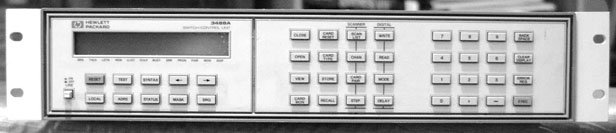
Why make when you can buy cheaper
and with a lot less effort. Below is an HP3488a switch -- these go for about $40 on the Bay with a card or two. (Originally they were about $3400). The 44470A relay card will switch 10 signals from up to 250 V, you can fit 4 cards in the switch. There is an analog card, a breadboard card, a video card, another relay card etc. It can be programmed over the GPIB/HPIB buss using a National Instruments card. You get a very high quality board, gold plated to the usual HP standard, excellent power supply, rack cabinet etc. They are inexpensive since they were used by companies like Cisco, Lucent and Nortel and a lot of this stuff is just disgorged onto the market. <p> Of course, the XYL factor may dictate that HPIB cables and PC's be kept out of the listening area, but this rarely stops DIY'rs. I daresay that you could probably fit an entire preamp within the space and provide all the controls with the 3488a (channel switching, volume, record, mute etc.)
and with a lot less effort. Below is an HP3488a switch -- these go for about $40 on the Bay with a card or two. (Originally they were about $3400). The 44470A relay card will switch 10 signals from up to 250 V, you can fit 4 cards in the switch. There is an analog card, a breadboard card, a video card, another relay card etc. It can be programmed over the GPIB/HPIB buss using a National Instruments card. You get a very high quality board, gold plated to the usual HP standard, excellent power supply, rack cabinet etc. They are inexpensive since they were used by companies like Cisco, Lucent and Nortel and a lot of this stuff is just disgorged onto the market. <p> Of course, the XYL factor may dictate that HPIB cables and PC's be kept out of the listening area, but this rarely stops DIY'rs. I daresay that you could probably fit an entire preamp within the space and provide all the controls with the 3488a (channel switching, volume, record, mute etc.)
Attachments
Try here for an example of a:- <a href="http://www.geocities.co.jp/Technopolis/5053/amp/t_att.htm">Fixed impedance type ATTENUATOR
<img src="http://www.geocities.co.jp/Technopolis/5053/amp/20kATT.gif"></a>
Its in Japanese, you may want to try <a href="http://www.worldlingo.com/wl/Translate">worldlingo.com</a> for a translation.
Some of the Values for R1 might prove hard to obtain.
Regards
James
<img src="http://www.geocities.co.jp/Technopolis/5053/amp/20kATT.gif"></a>
Its in Japanese, you may want to try <a href="http://www.worldlingo.com/wl/Translate">worldlingo.com</a> for a translation.
Some of the Values for R1 might prove hard to obtain.
Regards
James
Combined with the prohibitive cost of relays,
One thing I did recently was use AUTO relays ... I got some from Mouser for pretty cheap I needed 12v anyway (the xformer I have has a 12v secondary).
I was trying to get 30A relays for my OptiMOS home theater 2Kw power supply, and I was having a hard time finding them - so on a lark I got some $2 relays that'll handle that (probably were headlight or starter relays). They aren't physically very large, and I was trying to NOT get 'miniature' relays. I'm not sure how they sound yet, but I'm planning on using one relay per channel for the output relays. For the power supply soft start they are pefect of course.
I'm guessing here though, you need make before break, and I don't think these type of relays will work.
I've been following this thread with interest, and there's just a couple of comments I'd like to add...
Is the PGA2310 that bad?
I know that it isn't going to be as transparent as a passive solution - this goes without saying. But, I'm wondering about how you came to decide that it is as unacceptable as you say... During a past discussion in this thread, I asked some questions about power supply decoupling and capacitor type selection, and made some suggestions that might improve the sound quality. There was no response at the time, but did you get the chance to try them?
Constant-impedance attenuators
Already mentioned here, but in my view, this is the only way to go if you want to use relays... I've considered it myself in the past (albeit using analogue switches rather than relays)
It's simple, in theory. You decide on a system impedance (say, 600 ohms). Then, you build a number of attenuators that have a 600 ohm input impedance, 600 ohm output impedance, and the attenuation required. Eg, 1dB, 2dB, 4dB, 8dB, 16dB, 32dB... See the pattern?
Next, relays switch them in and out of circuit. You'll need a dual-pole relay for each channel... Therefore, they are cascaded until you have the required attentuation - this part of the maths is simple, because 4dB plus 8dB gives you 12dB
You need these so-called constant-impedance attenuators so that the attenuation of one isn't altered by the loading of the next one...
The hard part is choosing the resistor values for each attenuator. But, this information might already exist somewhere on the Internet...
So, just my 2 cents worth...
Seasons greetings
Indeed I did. It got kinda stuffy after a while...So you crawled out from under your mass of board orders did you?
JordanG:
Have a look at these parts:
Toshiba VHC164
Toshiba TD62083AF
Both ICs are available from DigiKey, and I've used them in concert before for a similar type of project. Indeed, logic gates are really not up to the task of reliably driving a relay coil, even if it's a pretty small one, so in general a driver transistor is needed to switch the coil currents. That's what the second IC is for. It's basically a bunch of OC (open collector) driver transistors in a compact package. I used it to drive LEDs, but relay coils work just the same.
The 74VHC164 is the SIPO (serial in parallel out) shift register device I used. All that's required is one data line and a clock to shift the data bits in. Quite simple, I think you'll agree, and much less hassle than a micro or I2C chip, although you may need to write a quick little software routine to do the bit-bashing. I don't think this particular chip can be daisy-chained, but you can see how easy it would be to control numerous banks of resistors with a bunch of daisy-chained SIPO registers... Plus, you can write data to this chip at 20HMz, or whatever speed your micro can muster, as opposed to the pokey 100/400kHz clock of I2C.
Regarding relay control, in general it does not matter if the coil is polarized. Because it's a coil, it is an inductive element, and that's all that matters. Shorting one end to ground with the other end tied to the supply voltage will cause a current through the inductor, hence storing energy in it's magnetic field. If you switch it off in a hurry, the inductance will try and force a current to flow, in the process generating whatever voltage it needs to dump this stored energy. This usually would result in overvoltage and destruction of your switching device, or maybe an arc inside a mechanical relay which would cause premature aging and failure. I suspect that your logic gates driving the relays are having their ESD protection paths exercised each time a relay turns off. All that's required to solve the problem is a diode in parallel with the coil. In normal operation, the diode is reverse biased, but when the switch turns off, the diode becomes forward biased, carrying the current being dumped by the coil, and thus preventing any excessive voltages from forming. Incidentally, many car ignition systems work the same way. A large coil is shorted between +12V and ground, building up a big current in the coil. Then, the coil is disconnected from ground, and the floating terminal jumps up to extremely high voltage in an effort to dump the coil's energy. At some point, it reaches a high enough voltage to arc across the spark plug's gap, and the coil's stored energy discharges through the ionized gas.
passive vol
Mark, can you tell me which switches you used, what were your impressions sound-quality wise?
Thanks,
Jan Didden
mhennessy said:[snip]... I've considered it myself in the past (albeit using analogue switches rather than relays)[snip]
Mark, can you tell me which switches you used, what were your impressions sound-quality wise?
Thanks,
Jan Didden
- Status
- This old topic is closed. If you want to reopen this topic, contact a moderator using the "Report Post" button.
- Home
- General Interest
- Everything Else
- Relay-based passive volume control project