With any relay/switch based approach, there will always be a small amount of switching noise. Yes, the scheme does provide the capability to do mbb.
The reason for my approach is to only have two resistors in the circuit, provide a constant impedence, and allow one to use transformers instead of resistors. Every solution has trade-offs. My intent was to provide the purist approach.
Dale
The reason for my approach is to only have two resistors in the circuit, provide a constant impedence, and allow one to use transformers instead of resistors. Every solution has trade-offs. My intent was to provide the purist approach.
Dale
jgwinner said:If it's MBB then you'd BRIEFLY have the same problem, a slight change in volume as the resistors go in parallel.
about 1ms,
and two resistors in parallel is prefrable to o/c
ATTENUATOR.
Hi,
Which is a very good idea in the first place- I use a constant impedance attenuator myself- just keep the shunt R constant and calculate the series R accordingly.
How you switch from one position to the other is best done with a MBB arrangement to avoid switching noise.
In practice you'll only hear the switches clicking...the better relays have mercury wetted contacts AKA Reed relays.
Any remote control is up to your imagination.
Simple as that,")
Hi,
The reason for my approach is to only have two resistors in the circuit, provide a constant impedence, and allow one to use transformers instead of resistors. Every solution has trade-offs. My intent was to provide the purist approach.
Which is a very good idea in the first place- I use a constant impedance attenuator myself- just keep the shunt R constant and calculate the series R accordingly.
How you switch from one position to the other is best done with a MBB arrangement to avoid switching noise.
In practice you'll only hear the switches clicking...the better relays have mercury wetted contacts AKA Reed relays.
Any remote control is up to your imagination.
Simple as that,
Good info on this thread. After starting on a project to build a microcontrolled ladder attenuator, I just discovered they can be very expensive. For e.g. 48 steps on a balanced stereo attenuator I need 192 relays ($386), four rather big circuit boards ($115), 5 each of 96 difference resistor values ($50), an encoder ($45), 24 '595 shift registers ($16), and of course the microcontroller ($5).
Bottom line: $617
That's a pretty dang expensive volume knob. I console myself with the knowledge that exactly nobody manufactures such an attenuator. Mine will be unique. Also ladder attenuators have constant impedance. Yay.
However before I cut a big check to Digi-Key I'd love to explore some of the designs here, which are a bit lower cost. The shunt looks like the best alternative to the ladder. With a fixed shunt and six relays per channel I get 64 steps and I only spend $219. Seems like a better allocation of funds.
What does the peanut gallery think?
Re: 8-bit relay control
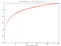
My graph came out like this (its just higher up in the thread).
I dunno about your graph jwb.. For starters, I was pretty sure it should stop at -48db..jwb said:Here is the plot of attenuation using eight resistors in powers of 2, just like the Aleph P 1.7
My graph came out like this (its just higher up in the thread).
Jordan, I took a look at ftorres' cascaded ladder attenuator design. I agree that his has superior usable range, but it also uses twice as many relays! After reading his article, I don't buy his logic about not doing the make-before-break when the LSB does 000->111 or 111->000. Unless my calculations are wrong (again), I think you can engage, for example, -70dB and -60dB dividers simultaneously to produce a -66.7dB divider of 25.0KΩ and 11.5Ω. You can also engage the 0dB and 8.75dB dividers to produce 0dB (duh). So, if you are going from -70dB to -68.75dB you stop by -66.7dB on the way there. Not too bad of a jump, I don't think.
Similarly going from -20dB to -18.75dB takes a stop at -25dB. Not too bad of a bobble. Certainly it isn't as bad as if you just let the relays flop, in which case you would go to mute between each setting.
The actual problem comes in when you are going from -10dB to -8.75dB. In this case you make a stop by -0dB on the way! This could be avoided by using separate latches for each bank of relays, and controlling their timing separately.
Finally I noticed that the -10dB divider seems wrong. It should be 34KΩ and 16KΩ, not 60.4KΩ as marked in ftorres' drawing.
- Status
- This old topic is closed. If you want to reopen this topic, contact a moderator using the "Report Post" button.
- Home
- General Interest
- Everything Else
- Relay-based passive volume control project