Thinking about this walking the dog this morning I think it is simply collapsing under load. I have a 10r and 8r in series for the test load and setting for 3v3 means a 183ma draw. I think there is maybe a 4r4 at R1 which can provide only about 130mA. It was previously set up for a small 50mA load. Hopefully a simple fix!
Yes its perfectly fine....tested with 30ohm and it gave 3.28v and on the actual load of the Fifo clean side (one of the clocks has its own psu) it gives bang on 3v3.
Yay!
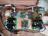
Busy with Salas in here. L-Ad for Pi 5v, one Ubib for Fifo dirty side, one Ubib for the Abraxalito Phidac, Reflektor D for Fifo clean .

Yay!
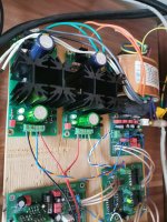
Busy with Salas in here. L-Ad for Pi 5v, one Ubib for Fifo dirty side, one Ubib for the Abraxalito Phidac, Reflektor D for Fifo clean .
I use 2xUBIB 1.3 and 2x Reflektor-D in AD1862 DAC. It was faster that way on my pcb. After assembly, all shunts started without error. Reflektor-D drifted only 0.02 Volts after an hour of operation. Excellent design and excellent sound. They replaced LT series linear controllers.....forever. The deep range has been expanded but remains tight and precise. The high range is a bit more lively but not intrusive or offensive. In short, excellent work.
Thank you Salas.
Thank you Salas.
Attachments

Hi,
No, that's not a good proposal from Digikey. We look for something with Vg(th) 2V max as the original's. So it can work for below 5V output settings too. I see IRL520PBF in stock both at Digikey's and Mouser's. Looks like fitting the replacement job description well. It also has similar internal capacitance specs to the original.
No, that's not a good proposal from Digikey. We look for something with Vg(th) 2V max as the original's. So it can work for below 5V output settings too. I see IRL520PBF in stock both at Digikey's and Mouser's. Looks like fitting the replacement job description well. It also has similar internal capacitance specs to the original.
Regarding post #11 from 2014....*The table has a left vertical axis that shows CCS (A) 0.6A corresponding to 1 Ohm R1 for 450mA advisable load. That means 600mA run in the reg as max current limit with R1 = 1 Ohm.
To Salas or anybody else who knows:
I'm intending to use the Reflektor to power a Crystal Oscillator that draws about 20mA. I'd like to set R1 higher than 2 ohms to minimize the heat dissipation. Thought I might try 2.5 or 3 ohms. How far can I go before there's trouble?
Thanks,
Hugh
Thanks Salas!No less than 100 mA spare current.
May I ask a couple of questions:
- is it normal to set R6 = 2SK880 (instead of 2SK117), or it is better to use some other JFETs
- for what purpose used separated S0, S+, F0 and F+ (from manual pdf it is not clear), with separated wires they could be twisted and it will be possible to use light or medium wire's gauge (instead of 12AWG + 5 sm length when only 2 wires)?
-R6 is a load resistor for the current mirror. J1 2SK117 through hole or 2SK880 SMD is a bias JFET element in the control loop for the M1 CCS Mosfet. There are alternative SMD J1 pads on the board. 2SK209 SMD can be also used.
-The four wires purpose is Kelvin principal remote sensing capability. S wires can be light gauge twisted wires, they carry no current. Its not advised to use Kelvin sensing for long wire runs because it can pick various noises due to this regulator's wide bandwidth. Can be locally cancelled at the output connector by shorting S+ with F+ and S0 with F0. To use it with normal two heavier gauge wires.
-The four wires purpose is Kelvin principal remote sensing capability. S wires can be light gauge twisted wires, they carry no current. Its not advised to use Kelvin sensing for long wire runs because it can pick various noises due to this regulator's wide bandwidth. Can be locally cancelled at the output connector by shorting S+ with F+ and S0 with F0. To use it with normal two heavier gauge wires.
no, I mean mod for R6 when set JFET R6 resistor vs JFET-R6 is a load resistor for the current mirror. J1 2SK117 through hole or 2SK880 SMD is a bias JFET element in the control loop for the M1 CCS Mosfet. There are alternative SMD J1 pads on the board. 2SK209 SMD can be also used.
for this place good choice: 2SK117 (obsolete), 2SK880 or 2SK209 ?
Ough, google sends on phrase "Kelvin principal remote sensing capability" to some GPS systems-The four wires purpose is Kelvin principal remote sensing capability. S wires can be light gauge twisted wires, they carry no current. Its not advised to use Kelvin sensing for long wire runs because it can pick various noises due to this regulator's wide bandwidth. Can be locally cancelled at the output connector by shorting S+ with F+ and S0 with F0. To use it with normal two heavier gauge wires.
") , what benifits from those S wires? Or it make sence to join them as realized in Reflektor Mini&Flexy?
, what benifits from those S wires? Or it make sence to join them as realized in Reflektor Mini&Flexy?- Home
- Amplifiers
- Power Supplies
- Reflektor-D builds