-Yes, that's the green one
-What do you mean "and replace M1 with MSFRF860G"? M1 is a Mosfet not a TO-220 diode
-Mount the DC Flexy's MSRFs to the chassis as well. They will be powering 1.5A regs* in total, that will make them hot enough if unassisted
*Assuming one DC Flexy shared between those two regs
Whoops, my mistake I meant FQP3P20
I'll use 1 DC Flexy per reg. probably no harm in mounting all 8 MSFRF860G
Tell me the secondary voltage of the transformer that you are going to use, before I can answer about the FQP3P20, because it has higher Vgs drop than the IRF9610 and I want to check there will be voltage space.
With one DC Flexy per reg, mounting the diodes to cool is not mandatory, but no harm either. Up to 1A they are reliable enough on their own if there is ventilation.
With one DC Flexy per reg, mounting the diodes to cool is not mandatory, but no harm either. Up to 1A they are reliable enough on their own if there is ventilation.
By the way a local friend who got some advanced test gear and tries to sort out a good resolution impedance automation set up and its routines for his lab, used the REF-D as one of his devices under test and found it the only reg to produce a flat output impedance plot up to 100kHz where his analyzer sampling limit allows. Including chip regs for DUT like the LT3042/3045.
Tell me the secondary voltage of the transformer that you are going to use, before I can answer about the FQP3P20, because it has higher Vgs drop than the IRF9610 and I want to check there will be voltage space.
With one DC Flexy per reg, mounting the diodes to cool is not mandatory, but no harm either. Up to 1A they are reliable enough on their own if there is ventilation.
It will be 9V AC but my mains AC always runs a little high so it will most likely be around 10.5V to 11V AC unloaded
There is enough voltage space for the FQP3P20 and J1 with that transformer even in the ~0.9A case. It may drop circa 6.4V Vgs between the raw DC input and J1 to ground in that case.
Should I use the IRF9610 instead to be safe? I will place a large over sized heatsink on it
Hello Salas, i need your knowledge regarding C2 cap.
i instaled a polymer cap from kemet. the specs are:
capacitance: 1000uf
voltage rating:10 VDC
esr:13 mOhms
ripple current:5.1 A
leakage current:1.5 mA
this is for power 3.3v of the clock and digital receiver.
is this cap ok for this propose?
thks
i instaled a polymer cap from kemet. the specs are:
capacitance: 1000uf
voltage rating:10 VDC
esr:13 mOhms
ripple current:5.1 A
leakage current:1.5 mA
this is for power 3.3v of the clock and digital receiver.
is this cap ok for this propose?
thks
Yes you may use it, C2 is the voltage reference filter cap, its ESR & ESL spec has no direct impact to the reg's stability. You may actually use much higher uF C2 than 1000uF without other problem than taking more time to charge up for set Vout at power on. The REF-D benefits from 300mA spare current for audio band lower Zo and lower THD on the rail from load interaction, while big C2 further benefits the below 10Hz Zo and noise. Clocks must like small below 10Hz Zo and noise. REF-D with JFET mod or REF-D Mini that has JFET mod as standard care less for hgh spare current and high uF C2. Because they are internally more dynamic in driving the output Mosfet, more so at very low Hz. REF-D without JFET mod has the easier smoother beyond audio band HF Zo extension, less reactive, but also more mΩ in general and especially below 10Hz (1/f).
Very small Zo as achieved by JFET mod can be easily spoiled by cabling, connectors, and copper lanes though. Both at the reg and at the load. In practical terms the Zo differences of regular REF-D and JFET mod REF-D are closer than with theoretical (simulation) analysis. But they do exist, especially at very low Hz.
Very small Zo as achieved by JFET mod can be easily spoiled by cabling, connectors, and copper lanes though. Both at the reg and at the load. In practical terms the Zo differences of regular REF-D and JFET mod REF-D are closer than with theoretical (simulation) analysis. But they do exist, especially at very low Hz.
Yes you may use it, C2 is the voltage reference filter cap, its ESR & ESL spec has no direct impact to the reg's stability. You may actually use much higher uF C2 than 1000uF without other problem than taking more time to charge up for set Vout at power on. The REF-D benefits from 300mA spare current for audio band lower Zo and lower THD on the rail from load interaction, while big C2 further benefits the below 10Hz Zo and noise. Clocks must like small below 10Hz Zo and noise. REF-D with JFET mod or REF-D Mini that has JFET mod as standard care less for hgh spare current and high uF C2. Because they are internally more dynamic in driving the output Mosfet, more so at very low Hz. REF-D without JFET mod has the easier smoother beyond audio band HF Zo extension, less reactive, but also more mΩ in general and especially below 10Hz (1/f).
Very small Zo as achieved by JFET mod can be easily spoiled by cabling, connectors, and copper lanes though. Both at the reg and at the load. In practical terms the Zo differences of regular REF-D and JFET mod REF-D are closer than with theoretical (simulation) analysis. But they do exist, especially at very low Hz.
Ok thks Salas for the help, i am using reflektor without jfet mod. How big can i go with c2?
I am building some boards with diferent caps... for now i have two.. and the sound is a bit different.. i going to build more. I have the stock one for comparing witch i like the sound very much.
There are up to 10000uF 6.3V low ESR relatively small capacitors for computers etc. Try 4700 & 10000uF to see if you like something with them. If SMD you can add legs as they have wide enough pads to stick things on. With 10000uF and 300mA spare the regular REF-D's Zo will be very nearly flat from 1Hz to 100kHz and the, already low noise, very well extra filtered. Clock should like that.
For those building a mini to power the BIII pro I would suggest building the LED test rig in the mini guide to see how the LED's behave with J2. The voltage does rise enough to the point where 2 yellow LED's would give me 5.02V. The green ones put me way over the max voltage for a BIII.
Attachments
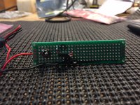
my pleasure... I'll post some build photos soonNice reminder and a nice rig photo
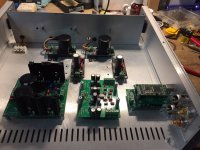
2 minis up and running. My advice is read and re-read the build guides until you understand them. Build the LED test rig. Most important, take your time.
The two yellow LED's puts out 5.12 Vdc on cold start up down to 5.06 Vdc warm (Chronos stack).
The one yellow and one red LED puts out 4.98 Vdc on cold start up down to 4.88 Vdc warm (BIII Pro).
Thanks to Salas and TB!
The two yellow LED's puts out 5.12 Vdc on cold start up down to 5.06 Vdc warm (Chronos stack).
The one yellow and one red LED puts out 4.98 Vdc on cold start up down to 4.88 Vdc warm (BIII Pro).
Thanks to Salas and TB!
Attachments
- Home
- Amplifiers
- Power Supplies
- Reflektor-D builds