I have to connect all of my newly populated boards together now. 
I have the 2-pin and 3-pin clips installed, just as you have Oliver, but I'm not entirely sure how to connect them all up:
1.) The power connections are all pretty clear I think. My only question here is regarding the earthing on the TDA boards. I have a v2.2 board and a v2.3 and the earths are different. Shall I add a jumper under the v2.2 to connect the analog and digital earths? I would have thought it better to connect them behind the power supplies, as in your original v2.2 plan. Won't that reduce ground line contamination from digital to analogue stages?
2.) Master/slave audio out connections. How is this best done please? I could just link them both together with the master/slave connectors, and then take audio lines out of the master, or else I could send wires from both outputs to meet the tube-I-Zator together, for perfect parallel speed constancy. What do you think?
3.) Similarly i2S connections. How is this best done please? Do I feed into the master, out the other side of the board and into the other input, perhaps? (or into the other output, would be a shorter journey....possible?)
4.) Has anybody wired up the Twisted Pear S/PDIF transport yet?
Sorry for all the questions...soon I will post lots of nice pictures of my working DAC, I hope!
Hi Lucas,
to your questions:
I would recommend to set the jumper on the supply input side.
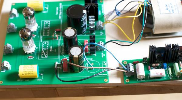
If you could, just link them on the left Master/Slave connectors and feed the Tube-I-zator from one of the Audio out connectors.
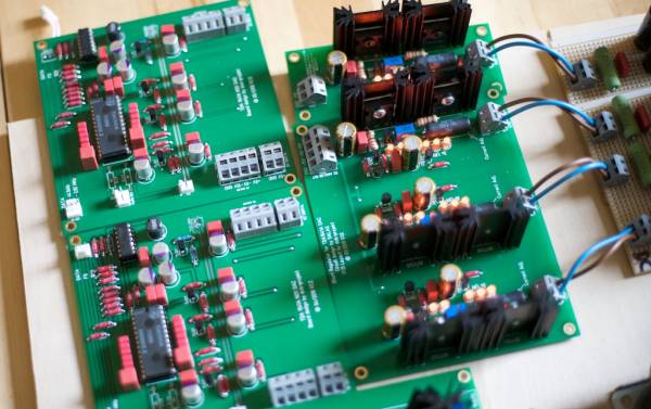
Connect them like on my photo.
I must do it next week....
to your questions:
1.) The power connections are all pretty clear I think. My only question here is regarding the earthing on the TDA boards. I have a v2.2 board and a v2.3 and the earths are different. Shall I add a jumper under the v2.2 to connect the analog and digital earths? I would have thought it better to connect them behind the power supplies, as in your original v2.2 plan. Won't that reduce ground line contamination from digital to analogue stages?
I would recommend to set the jumper on the supply input side.
2.) Master/slave audio out connections. How is this best done please? I could just link them both together with the master/slave connectors, and then take audio lines out of the master, or else I could send wires from both outputs to meet the tube-I-Zator together, for perfect parallel speed constancy. What do you think?
If you could, just link them on the left Master/Slave connectors and feed the Tube-I-zator from one of the Audio out connectors.
3.) Similarly i2S connections. How is this best done please? Do I feed into the master, out the other side of the board and into the other input, perhaps? (or into the other output, would be a shorter journey....possible?)
Connect them like on my photo.
An externally hosted image should be here but it was not working when we last tested it.
4.) Has anybody wired up the Twisted Pear S/PDIF transport yet?
I must do it next week....
1541 DAC is running :-D
Good evening gentlemen,
could finish my DAC today and let it some nice music play. No smoke, no hum, just music. I'm using Olivers shunts and the DAC board of course (without TL431), self brewed rectifier boards with Johns nice stepped rectifiers, Doedes SPDIF receiver board and Johns latest outputstage. Very promising sound for just brand new parts. Looking foreward to hearing really perfect sound after having had running the item for a few hours and doing a nice shootout vs AD1865
Thanks Oliver for your work!
Ernst
Hi Lucas,
to your questions:
I would recommend to set the jumper on the supply input side.
If you could, just link them on the left Master/Slave connectors and feed the Tube-I-zator from one of the Audio out connectors.
Connect them like on my photo.
An externally hosted image should be here but it was not working when we last tested it.
I must do it next week....
Thank you once again Oliver. Sorry though, I'm still not clear about the i2S. Perhaps I am being stupid.
The photo doesn't help me much, as I don't really know what the wires are or where they go. I am presuming that on the right, in the output, you actually have the input from the Teralink X2. If so, what are the other two wires departing in the black sleeve for please? I am presuming that on the other side (left) is a simple jumper between the two boards' i2S. Is that right?Many thanks
Thank you once again Oliver. Sorry though, I'm still not clear about the i2S. Perhaps I am being stupid.
Many thanks
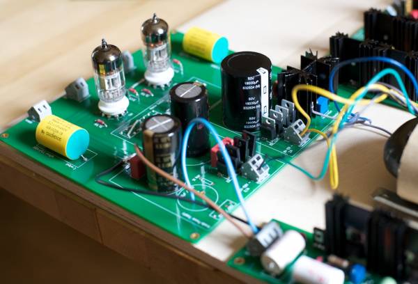
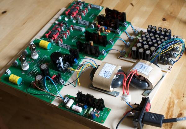
Correct. My two DAC modules are on top of each other.
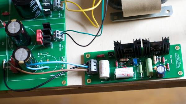
The right I2S connector comes from the X2, the left is the jumper between the pcb´s.
The Audio out goes to the Tube-I-zator and the Master/Slave is also a jumper between the pcb´s.

Good evening gentlemen,
could finish my DAC today and let it some nice music play. No smoke, no hum, just music. I'm using Olivers shunts and the DAC board of course (without TL431), self brewed rectifier boards with Johns nice stepped rectifiers, Doedes SPDIF receiver board and Johns latest outputstage. Very promising sound for just brand new parts. Looking foreward to hearing really perfect sound after having had running the item for a few hours and doing a nice shootout vs AD1865
Thanks Oliver for your work!
Ernst
Congratulations Ernst
Thats good news......Some pics would be nice
Alon
Congratulations Ernst
...Some pics would be nice
Alon
Yes congrats Ernst.
Thanks for the flowers
Will try my best regarding some nice photos. Soundwise the sun slightly appeared today - waiting for more
Sound of Johns OS seems to be on the dry side, very dry. We will see and hear.
Cheers Ernst
Hi,
for the salas regulator, is it possible to use IRF 9540 and IRF 540. the price is very low compare to IRFP 9240 and 240
MOSFET CANAL P 23A 100V TO262 IRF9540
International Rectifier | Semiconducteurs | Discrets | MOSFET | Transistors MOSFET et JFET - CANAL P |IRF9540NLPBF
Trans MOSFET N-CH 100V 28A
Vishay | Semiconducteurs | Discrets | MOSFET | Transistors MOSFET et JFET - CANAL N |IRF540PBF
Thanks
Philippe
Where I'm up to:
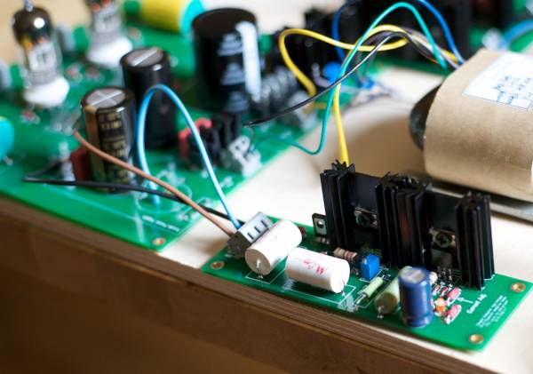
Shunt reg for HV seems to be working well. Hot 840 though - may need a bigger sink!
Tube-I-Zator tested for voltages, but not sound yet....watch this space!
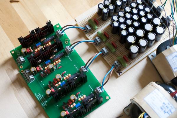
The DAC shunt regs, all working very well indeed. -15v is quite a bit hotter than the 5v and -5v regs.
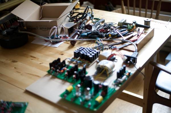
The mess my wife's been putting up with. (Actually moaning about quite a lot.)
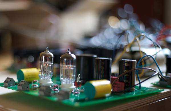
Waiting on standoffs to mount the boards, and the USB to 12S converter.
Shunt reg for HV seems to be working well. Hot 840 though - may need a bigger sink!
Tube-I-Zator tested for voltages, but not sound yet....watch this space!
The DAC shunt regs, all working very well indeed. -15v is quite a bit hotter than the 5v and -5v regs.
The mess my wife's been putting up with. (Actually moaning about quite a lot.)
Waiting on standoffs to mount the boards, and the USB to 12S converter.
Last edited:
Hi,
for the salas regulator, is it possible to use IRF 9540 and IRF 540. the price is very low compare to IRFP 9240 and 240
MOSFET CANAL P 23A 100V TO262 IRF9540
International Rectifier | Semiconducteurs | Discrets | MOSFET | Transistors MOSFET et JFET - CANAL P |IRF9540NLPBF
Trans MOSFET N-CH 100V 28A
Vishay | Semiconducteurs | Discrets | MOSFET | Transistors MOSFET et JFET - CANAL N |IRF540PBF
Thanks
Philippe
Hi Philippe,
here is Salas answer to your question:
9520 for CCS, 9540 for shunt position, yes. 9540 is too slow for the CCS when its strong enough for the shunt use.
Best,
Oliver
Nice one Lucas...its looking good
I have got my diodes, I/V and Cathode Resistors, so im just waiting on my transformer
I also ordered 2 mark grant mains leads(for source(Cambridge Audio 840c) and dac) and a mark grant digital cable. Is that a mark grant mains lead i see in your photo's Lucas?
I am dying to get this dac up and running...How is the sound coming along Ernst? Any more rays of sun?
Alon
Last edited:
Thanks Alon,
I'm not sure where the power cable originated, other than "eBay".
Oliver, could you explain how to wire the i2S on the Teralink X2 to TDA board please. I am going crazy trying to find information on how to set this thing up. The pinout on the X2 box doesn't relate to the 3 pins very obviously other than the DATA pin, which is the same. So, I have 3 questions:
1. What on the X2, out of options MCLK, LRCK and SCLK relates to FS and BCK please?
2. Also, do I tie all the GNDs from X2 together and send them to the digital GND?
3.To play from iTunes on the mac, do I need to do anything to get the iTunes to output to the USB cable? I need to hear this thing!!!!!
Many thanks
Lucas
Thanks Alon,
I'm not sure where the power cable originated, other than "eBay".
Oliver, could you explain how to wire the i2S on the Teralink X2 to TDA board please. I am going crazy trying to find information on how to set this thing up. The pinout on the X2 box doesn't relate to the 3 pins very obviously other than the DATA pin, which is the same. So, I have 3 questions:
Many thanks
Lucas
Hi Lucas,
1. What on the X2, out of options MCLK, LRCK and SCLK relates to FS and BCK please?
SCLK to BCK
LRCK to FS
DATA to DATA
2. Also, do I tie all the GNDs from X2 together and send them to the digital GND?
Yes
3.To play from iTunes on the mac, do I need to do anything to get the iTunes to output to the USB cable? I need to hear this thing!!!!!
No. Just go to "System-Sound" an look if you see the X2 in the sound output setting.
What you additional can do is to go in the Audio-Midi Setup and switch the X2 sampling frequency to 48.000 Hz to run the internal chip without any sampling rate conversion.
Best regards,
Oliver
OK, so the Teralink X2 wasn't appearing due to a brand new 5 metre USB cable not working. Grr.
I have a shorter cable and it works fine, appearing in Audio Output of System Preferences.
Now, still no music. From the Teralink X2 to the TDA board I have the three wires as you said, and with my multimeter I can confirm both 44.1Khz and 48Khz (depending on how it is set up) and also the 2.82 Mhz (give or take a bit of inaccuracy) so I know that they are both correct.
I am now trying to work through to find which part of the whole DAC is not functioning. How can I confirm the DATA is coming through from the X2 please? I'd like to get that out of the way first.
If it is, then I have a problem on my TDA board or Tube-I-Zator I guess...
- Status
- This old topic is closed. If you want to reopen this topic, contact a moderator using the "Report Post" button.
- Home
- Group Buys
- "Reference" TDA1541A DAC with I2S-BUS architecture