I'm using a iMac and for virtualization parallels not vmware. With parallels it's no problem to use a terminal program to program the dam. Must be the same with fusion.
The adapter must be recognized by mac os, then it's possible to assign the port to the virtual machine (within control panel from parallels/fusion). Then windows will install the driver and the adapter can be used by a terminal program.
But it's also possible to use a mac os terminal program for the dam for example ZTERM.
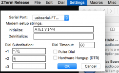
The serial adapter can be choosen from SETTINGS / MODEM PREFERENCES.
To choose in the first field. If the adapter isn't shown, the adapter ist not recognized. Then you have to install drivers.
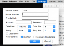
Speed must be set in SETTINGS/CONNECTION
To choose in the first field. If the adapter isn't shown, the adapter ist not recognized. Then you have to install drivers.
Speed must be set in SETTINGS/CONNECTION
Attachments
Hi,
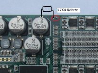
Can anyone let me know what's the value of the resistor in red circle in below photo?
Mine is dam1021 with a number 141021 which looks like a date?
Thanks
6K04 1% 0603. Your dam1021 is a rev1.
6K04 1% 0603. Your dam1021 is a rev1.
Thank you Soekris!
Asimetric output !!!
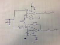
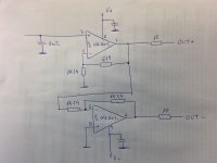
I have extracted schematic for V4 output.
As far I can see it has asymmetric gain, 1,5 for positive raw and 1 for negative.
While it is possible to drive a balanced line with an unbalanced signal, I suggest to change negative feedback resistor on inverted opamp to 1,86K. This will increase gain for negative rail to 1,5, therefore balanced signal will be symmetric.
Regards,
Tibi
Attachments
Hi
it is not asymetric... gain on inverted input is different formula as noniverted")
Instead 619 (1,2pin) use bigger resistor in the same relation 1,24 kohm ( 6,7 PIN) on other output. But than your gain will be higher also on xlr output.
For my taste opa1602 (opa1622) is tooo soft sounded opamp...Soekris is soft and relaxed from default. Therefore for more dynamic sound i will use another opamp. Or different output stage. If you need just rca than the job is easier.
it is not asymetric... gain on inverted input is different formula as noniverted
Instead 619 (1,2pin) use bigger resistor in the same relation 1,24 kohm ( 6,7 PIN) on other output. But than your gain will be higher also on xlr output.
For my taste opa1602 (opa1622) is tooo soft sounded opamp...Soekris is soft and relaxed from default. Therefore for more dynamic sound i will use another opamp. Or different output stage. If you need just rca than the job is easier.
Hi
it is not asymetric... gain on inverted input is different formula as noniverted
...
I know very well this and is still asymmetric.
Regards,
Tibi
I have extracted schematic for V4 output.
As far I can see it has asymmetric gain, 1,5 for positive raw and 1 for negative.
While it is possible to drive a balanced line with an unbalanced signal, I suggest to change negative feedback resistor on inverted opamp to 1,86K. This will increase gain for negative rail to 1,5, therefore balanced signal will be symmetric.
Regards,
Tibi
Your schematic is wrong, the input to the inverting opamp is taken from the output of the non inverting opamp, so the balanced output is symmetric....
....
Hi Soekris,
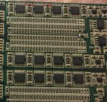
I have dam1021 rev1, and I'm trying to do the 16 caps mod.
Soekris DAC: Modding VRef | H i F i D U I N O
I found those holes in the PCB are very tiny, and around half of those holes were covered by PCB paint I guess and can't even put a single copper thread through it.
So, my question is, seems those holes are not connected to other parts, right? Can I expand those holes using a tiny drill bit?
Thanks!
Attachments
- Home
- Vendor's Bazaar
- Reference DAC Module - Discrete R-2R Sign Magnitude 24 bit 384 KHz