This is by far the input card i liked best so far. BUT the thing with 34/26 pin ribbon connector seems less good.. i would rather like it to fit with 26pin female straight over the dac input. I would rather put the other extra 8 pins in a separate connector to the side.
Doesn't that seem a bit better to do?
I drew up this board while waiting for the DAC to arrive, now that I have played with it for awhile, I'm rethinking some construction details.
Originally I was planning to use the onboard XLR connectors and to have all connectors out on the back panel. So the input board would go side by side with the DAC. The width of this board is made to fit in a Modushop Galaxy 230mmx230mm case, with enough space left for IEC power connector.
However, after some listening and comparing the buffered and unbuffered outputs, I am not so keen on using the onboard buffers any more. And if I don't use the onboard XLR connectors, then it makes sense to stick the input board directly on the J3 header.
The computer source I'm planning to use has a highly slimmed-down Windows XP and cMP/cPlay setup. The entire Op System, player, GUI, and Juli@ driver are on a <15Mb load. USB functionality is entirely removed, along with anything else not needed to run that setup.
The Juli@ mods are my own. It only uses the digital section and they include:
1. Cutting the PCI power and running it from a separate linear supply.
2. Adding additional bypass capacitors at each chips power feed... almost 2000uf added there. Caps are chosen to some extent by location, with PPS caps used instead of ceramic where they made a difference.
3. Separate modified Dexa regulators for the 5v and 3.3v rails on the card along with additional capacitance at the input and outputs of the regulators.
4. Disabling or removing non-used chips.
This took several iterations to get to where I was satisfied. I can provide you details off the list if you want. I never published it after I realized it took really good skills doing manual SMD soldering... above what I suspect most can do.
Ditto. I think there's a lot of untapped potential here in just playing with filters.
Greg in Mississippi
mods makes sense
how do you get the i2s from julia@ to the dac without long cables or losses/unwanted gains
you never posted your julia@ card mods anywhere?
Soren,
I'm looking at alternate output buffers. Would you be willing to post the stock output stage setup? I've got several to try, but I'd like to build an off-card set of yours so I can assess if there is any difference with separate power supplies. That would also give a good control starting point. TIA!
I will be mounting the DAM right on the Juli@ in place of the analog card. I2S lines will be MUCH longer than I like, between 50mm-100mm, depending on which end is towards the backplane. I'm looking at some alternatives, but I don't have sufficient room to mount the DAM with the long-axis vertically, which could provide the <10mm I prefer.
No, I didn't post them... sorry! They take some tricky SMD soldering. I realized few could do them successfully. But I'm very happy to share them. I can send details via your DIYAudio email link, if you'd like.
I had done several versions of more basic mods to that card in the past. That last mod-set was a larger subjective difference than all of the previous ones together, including powering the card separately (and both used the same linear supplies).
Greg in Mississippi
I'm looking at alternate output buffers. Would you be willing to post the stock output stage setup? I've got several to try, but I'd like to build an off-card set of yours so I can assess if there is any difference with separate power supplies. That would also give a good control starting point. TIA!
mods makes sense
how do you get the i2s from julia@ to the dac without long cables or losses/unwanted gains
you never posted your julia@ card mods anywhere?
I will be mounting the DAM right on the Juli@ in place of the analog card. I2S lines will be MUCH longer than I like, between 50mm-100mm, depending on which end is towards the backplane. I'm looking at some alternatives, but I don't have sufficient room to mount the DAM with the long-axis vertically, which could provide the <10mm I prefer.
No, I didn't post them... sorry! They take some tricky SMD soldering. I realized few could do them successfully. But I'm very happy to share them. I can send details via your DIYAudio email link, if you'd like.
I had done several versions of more basic mods to that card in the past. That last mod-set was a larger subjective difference than all of the previous ones together, including powering the card separately (and both used the same linear supplies).
Greg in Mississippi
@Soren: You can directly contact with Tom Browne (enquiries@sonicillusions.co.uk) he has great knowledge and can help you.
Tom knows about everything there is to know about discrete dacs. And he has a crowd of Starlight Dac users to prove it. He doesn't like FPGAs though and his dac accepts 44.1 only. Usually he is very informative but as this dac is a competitor, I don't know. Also he's quite busy now working on his RIAA.
Btw. his dac uses the PMD100 digital filter chip.
Hot.
Guys, this is one of the hottest threads around, and it can only improve. Thanks a lot to Soren for his mighty effort.
I know most of us have our own little secrets (or at least we think so) to "improve" the souncard or DAC, but most importantly, it seems Soren is open to evaluate good advices or ideas.
For example, next batch could have provision for connecting independent supplies for the different sections, in case we want to experiment, or even better, provide holes for those brave enough who would like to swap the SMD resistors for low noise R, like Vishay Foil, at least for the MSB.
(Group Buy?)
Keep the good work and good luck!
M.
Soren,
I'm looking at alternate output buffers. Would you be willing to post the stock output stage setup? I've got several to try, but I'd like to build an off-card set of yours so I can assess if there is any difference with separate power supplies. That would also give a good control starting point. TIA!
Greg in Mississippi
The output buffers are not the secret sauce, so here they are....
Attachments
Tom knows about everything there is to know about discrete dacs. And he has a crowd of Starlight Dac users to prove it. He doesn't like FPGAs though and his dac accepts 44.1 only. Usually he is very informative but as this dac is a competitor, I don't know. Also he's quite busy now working on his RIAA.
Btw. his dac uses the PMD100 digital filter chip.
Is there a soft emulation of the rom PMD100 filter chip somewhere ?
Does Pacific Microsonic still exist ? (free use possible ?)... Many testimonied very good sound with old multibit dacs ! Coud it be possible to the FGPA to select a filter strategy with low sample rate and an other with higher sample rate a little as the filter text file Soren gave ? Sorry if poor understanding of me !
@ Maxlorenz,
Hello Max, did you buy a dam1021 ?
Last edited:
Thanks Soren!
So it looks like this?:
Do I need the 1K resistor?
The 1K resistor and 0.1uF capacitor form a low pass filter with a corner frequency of 1560Hz on the 1.2V power supply. This will stop HF noise on the +1.2V rail feeding back into SPDIF inputs.
Add: Looking at your schematic, put the 0.1uF between power and GND back in the circuit - otherwise you just short circuit the 1.2V supply to GND.
Last edited:
Does Pacific Microsonic still exist ? (free use possible ?)...
Microsoft purchased all of Pacific Microsonic's IP in 2000 and is the current assignee of the Pacific Microsonic patents. Free use very, very unlikely.
The output buffers are not the secret sauce, so here they are....
Many thanks, Soren. And I'd NEVER ask you for your secret sauce... I can guarantee I'd never know what to do with it!
Later!
Greg Stewart
ah ! wait a minute, I have to recover the number of Bill I have somewhere...
Bill is very big on charitable giving - maybe if you register as charitable organisation he'll gift you the HDCD patents
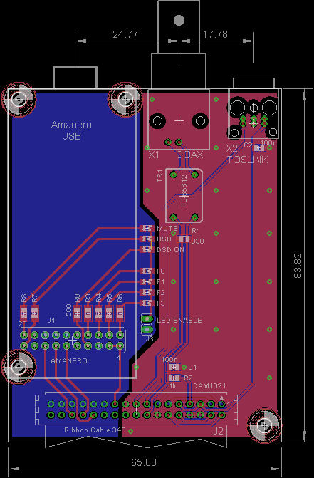
I have drawn up a version of an input board for Amanero, BNC Coax and TOSLINK inputs, but am now rethinking that TOSLINK should be powered from a separate supply..........
Looks complete and easier for Amanero user.
The only thing missing is some u.fl connectors beside the output pins. If this proceed into GB, WaveIO, Sonor, Joro card users will be out of luck.
I drew up this board while waiting for the DAC to arrive, now that I have played with it for awhile, I'm rethinking some construction details.
Originally I was planning to use the onboard XLR connectors and to have all connectors out on the back panel. So the input board would go side by side with the DAC. The width of this board is made to fit in a Modushop Galaxy 230mmx230mm case, with enough space left for IEC power connector.
However, after some listening and comparing the buffered and unbuffered outputs, I am not so keen on using the onboard buffers any more. And if I don't use the onboard XLR connectors, then it makes sense to stick the input board directly on the J3 header.
normundss, I'm looking forward to the directly on the J3 header.
I believe the patents have expired
M$ are unlikely to open source the code regardless of whether patents have expired or not.
All it means is if you want to attempt to reverse engineer the code from the parent disclosures you are free to do so.
You might want to send the schematics to me, just to check....
Hi soekris, I use the same schematic in the HifiDuino website (https://hifiduino.files.wordpress.com/2015/01/spdif1-2-2.jpg) with the additional LDO 3,3V for the Toslink (ADP150 with 2 decoupling X7R 16V 10uF).
I will prepare the schematic and I will send you.
My apologize to pollute your thread with this board. Actually my need is just the U.FL. connection to the I2S but looking in the above schematic I was supposing that should be useful for others diyers to have all in the same board.
Now I see that rredline make a very nice board
up and I am thinking that I will just realize the small board with the U.FL. that I need.Best Regards,
Enrico
DA101C and PE-65612 pads are quite similar, I think PE-65612 pads can be removed.
There is a datasheet for SC trafo on PC's site (not the exact model but solder pads should be the same):
digital_scicon
BTW, is your board equiped with a female connector so that it can be plugged into Soekris DAC's male input connector (see the pics below) ? May be 1 or 2 standoffs are needed at the Coax/Toslink connector side to provide stability. Thanks.
Hi rredline,
Thanks for the link...
Your board is very well done and can support the Amanero that as I understand is the most used.
For my configuration with the Edel_NMR I need just the 3 U.FL. connectors and the external 3,3V that I already have.
So, I think that is not more sense for me to go ahead with the design of the board. I don't have any interest to run a GB if cannot help the community.
All the Best,
Enrico
PS: almost forget, the board will be plugged into the 26pin connector of the DAC and I think that 4 cm of board will no need any standoff.
- Home
- Vendor's Bazaar
- Reference DAC Module - Discrete R-2R Sign Magnitude 24 bit 384 KHz