I'm sure you have seen this already, but just in case....
Sinc function - Wikipedia, the free encyclopedia
The sinc function looks like an excellent approach to reducing ringing. I'm sorry, but I'm no help in implementing it into a filter.
Also see Wikipedia "Reconstruction Filter" and the Common Filters section which talks about windowed sinc filters and higher order versions without ringing. Please note that this is typical Wikipedia and suited to someone like me that is new to the topic.
Is there any enough information on the TotalDac website about how they manage the filter ? NOS with some correction made in the highers frequencies with FIR to stay flat till 20 Khz iirc ! more than 60 bits here, does the 28 bits enough to do that on the dam1021?
Is there any concern about the output phase also ?
Can I ask you which voltage s you used from your power supply, please?
2 x 10V
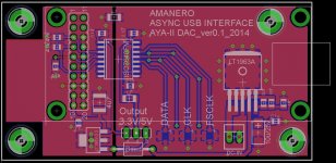
Hi emyeuoi, if you make an input and options PCB, maybe you could add my own version of the Amanero interface PCB which includes power supplies, insulator and U-FL connectors as well. See picture. I'm using Eagle PCB full release, but with such a small PCB you can certainly use the free version of Eagle. I can send you my design file and you can add it to the rest of you board. Just an idea. Let me know if interested.
Attachments
Just had a look of the TotalDac. It seems to me that some of the major differences (ok I'm just looking at the pictures here) are a second pcb with major PCB upgrade and possibly more sophisticated output section. And naturally massive use of nude vishay resistors for the R-2R resistors (very expensive design choice). Anyone had ever see the TotalDac under PCB? 6Moons has a few good pictures of it: http://www.6moons.com/audioreviews/totaldac/3.html
Last edited:
I also ran across this book, free to download. Seems to get into a lot of the filtering questions that were being asked.
The Scientist and Engineer's Guide to Digital Signal Processing's Table of Content
The Scientist and Engineer's Guide to Digital Signal Processing's Table of Content
The GB will be a good idea but I would like to complete the design first and share here the layout for any suggestion, mistakes, etc...
Hi Enrico, it seems like it might be a popular move to run a group buy for your input board.
My eventual use of the Soekris DAC will be via I2S only so I've no need of the facilities offered by your board myself.
Cheers
Ray
It’s running at last! Listening to it with headphones (Beyerdynamic DT-880) through buffered outputs single ended and sounds pretty good to me. Inputs are Amanero and toslink. Weak bass improved and harsh treble mellowed in few hours since initial start.
But I have a problem getting serial communication work. I’m on Mac, tried ZTerm and CoolTerm but I think I’m not using them properly. Can somebody please help?
* Using Aten UC-232A USB to serial converter. Installed driver (a challenge on its own) and both ZTerm and CoolTerm can detect it.
* Wiring should be correct, triple checked. DB-9 connector pins were numbered, so wrong connection is very unlikely.
* I got 6.2V between ground (pin 5) and TX (pin 3) and 0V between ground and RX (pin 2) on the DB-9 connector. If this is correct, it should wake serial port up on the DAC.
With CoolTerm, I can connect to the DAC. But I don’t receive any reply after I send “+++” command. The LED on the USB to serial converter flashes when command is sent.
With ZTerm, I can’t see a “connect” button at all. But connection timer starts running as soon as it launches with USB being the default device. I tried “dialing” but it didn’t help.
What am I missing?
I’m on Mac, tried ZTerm and CoolTerm
Also tried Serial (https://www.decisivetactics.com/products/serial/), still no response from dac. This is the most user friendly application of them.
Nice design!
Probably can add a 3.3V LDO for Toslink and draw 5V from the DAC?
Together with u-fl, you might also consider adding solder pads for the more durable SMA connectors, I heard Ian is heading that way in his new board.
Some people might need AES/EBU input, too.
Thanks for the suggestions...
- The 3,3V LDO is a good idea, easy to implement and do not take to much room in the board.
- To add the SMA connectors I need to make the board longer and obliged to add the standoffs. If it's not a "must to have" I will avoid them.
- For the AES/EBU input again I need to make the border longer to include the big XLR connector. The best solution should be to add the pads for the second input wires and the relevant resistor and let the XLR outside the board? I will make some trials
Regards,
Enrico
Looks good! I don't know if it's necessary, but you may want to include an inductor at the toslink receiver. Also, I know when I've worked with i2s I needed to keep my lines as short as possible, so it might be better if the uFL pads could be even closer to the connector pin outs--but I'd totally defer to people with more experience in this. I'd want one of these boards too!
Thanks picovolt.
The inductor (L1) is there. It is a smd 47 uH, 35 mA. I don't have experience with the Toslink, if some one have some more specific for the inductance please let me know.
You are right about the U.FL connectors and in the first design they was just under the 26 pin connector (J3 in the Soekris design) but I moved in the actual position when I add the transformer for the SPDIF. I can move them in the upper side of the J3 but they will look inside the DAC board and may be will be difficult to connect with the source? Also, the U.FL connectors need some free space to be connected with U.FL cables.
The other chance, that I prefer, is to move back near the J3 but under the board.
Regards,
Enrico
With ZTerm, I can’t see a “connect” button at all. But connection timer starts running as soon as it launches with USB being the default device. I tried “dialing” but it didn’t help.
What am I missing?
For ZTerm:
Go to Dial > Directory
Click "New"
Create a config with name "Soekris R2R", Data Rate "115200", Data Bits "8", Parity "None", Stop Bits "1" Flow control options all deselected. Select Local Echo if you want to see what you've typed.
Click "OK"
Got to File > Transfer Convert and select "Binary Data" - the default "Smart MacBinary" corrupts transfers.
To connect select "Soekris R2R" from the Dial menu. You should see "Direct Connect Soekris R2R" in the terminal window.
Also make sure you connect TX on the adapter to RX on the board, and RX on the adapter to TX on the board. You need to have the cable wired as a cross-over configuration for to work.
cheers
Paul
Last edited:
Hi All,
Thanks for your comments and suggestions so far.
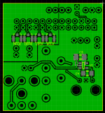
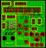
Attached are the print screens of the interface board (top and bottom sides) that I would like to submit for your additional checks and comments.
I added the LDO 3,3 V for the Toslink connector in the bottom side of the board. The +5 V are to be supplied by the dedicate connector. Adding the dedicated LDO to the Toslink connector I think that the 47 uH is not more required and I remove it but I am not an expertise about the Toslink, so please correct me if I am wrong.
I move the U.FL connectors in the bottom side of the board to have the traces as short as possible and in same time to have the room to properly connect the U.FL cables.
I added the connector for the POT
I added the pads for the balanced input transformer and the relevant pads for the XLR connector. The connector is not in the board... sorry, too big.
I move the following in upper side of the board: the switch for the 2 SPDIF inputs, the LED and the inputs that I don't know for what they are required.
The board size now is 39 X 42 mm.
Any comment, correction, etc.. are welcome") .
.
Thanks and Regards,
Enrico
Thanks for your comments and suggestions so far.
Attached are the print screens of the interface board (top and bottom sides) that I would like to submit for your additional checks and comments.
I added the LDO 3,3 V for the Toslink connector in the bottom side of the board. The +5 V are to be supplied by the dedicate connector. Adding the dedicated LDO to the Toslink connector I think that the 47 uH is not more required and I remove it but I am not an expertise about the Toslink, so please correct me if I am wrong.
I move the U.FL connectors in the bottom side of the board to have the traces as short as possible and in same time to have the room to properly connect the U.FL cables.
I added the connector for the POT
I added the pads for the balanced input transformer and the relevant pads for the XLR connector. The connector is not in the board... sorry, too big.
I move the following in upper side of the board: the switch for the 2 SPDIF inputs, the LED and the inputs that I don't know for what they are required.
The board size now is 39 X 42 mm.
Any comment, correction, etc.. are welcome
.Thanks and Regards,
Enrico
Attachments
With ZTerm, I can’t see a “connect” button at all. But connection timer starts running as soon as it launches with USB being the default device. I tried “dialing” but it didn’t help.
What am I missing?
I used the Terminal (in Application/Utilities) and the screen command essentially as described here:
Connecting to the serial console - Soekris Info Wiki
Updating Bios - Soekris Info Wiki
You need to know the "name" of your adapter first. You find it listed in /dev
(type "ls /dev/" in the terminal to list its content, then look for someting like
tty.usbserial-xyz
Then type in the terminal window
screen /dev/tty.usbserial-xyz 115200 8N1
If you get then an empty terminal window all worked fine and you can type the +++
If you power up the DAM after the serial connection is made you will see somthing like
I3
V-37
send by the DAM.
If you want to use screen for upgrading the firmware you have to install
"lrzsz" from MacPorts (and MacPorts https://www.macports.org) first.
Getting serial communication work
Thank you very much Paul & zfe. I got it working now.
For future reference:
1. Crossover wiring is required (TX/RX, RX/TX)
2. Power up dac AFTER connecting serial cable
3. Full power cycle is needed after firmware update (otherwise firmware version remains at previous one): Disconnect and reconnect BOTH dac power cable AND serial cable
For those who use a Prolific chip based converter on Mac:
1. Download latest driver from Prolific themselves (as of 02/2015): Drivers
2. Follow these steps in order to fix it: https://rolande.wordpress.com/2012/...usb-serial-adapter-working-with-mac-osx-lion/
I tried installing original drivers from Aten but Yosemite didn’t allow them to load. And you only know it didn’t when you check Console system logs!
Again many thanks gentlemen!
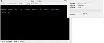
For some reason PuTTy never gets to transfer the new firmware file. Tried it several times. Just keeps hanging until the connection times out. Is this a power saving issue on the dac?
Are you pressing Enter after typing "download"?
Hi All,
Thanks for your comments and suggestions so far.
Attached are the print screens of the interface board (top and bottom sides) that I would like to submit for your additional checks and comments.
I added the LDO 3,3 V for the Toslink connector in the bottom side of the board. The +5 V are to be supplied by the dedicate connector. Adding the dedicated LDO to the Toslink connector I think that the 47 uH is not more required and I remove it but I am not an expertise about the Toslink, so please correct me if I am wrong.
I move the U.FL connectors in the bottom side of the board to have the traces as short as possible and in same time to have the room to properly connect the U.FL cables.
I added the connector for the POT
I added the pads for the balanced input transformer and the relevant pads for the XLR connector. The connector is not in the board... sorry, too big.
I move the following in upper side of the board: the switch for the 2 SPDIF inputs, the LED and the inputs that I don't know for what they are required.
The board size now is 39 X 42 mm.
Any comment, correction, etc.. are welcome
Thanks and Regards,
Enrico
I think it would be more flexible if the u.fl's were on the upper side of the board, and the other side of the 26-pin connector. if it's hard to get room for them, then move the 3,3V and FSEL connectors a bit lower down, and rotate them 90 degree, then place the MCKL u.fl above them.
this is at least what i think would be best - but we all think different
Thank you very much Paul & zfe. I got it working now.
For future reference:
1. Crossover wiring is required (TX/RX, RX/TX)
2. Power up dac AFTER connecting serial cable
3. Full power cycle is needed after firmware update (otherwise firmware version remains at previous one): Disconnect and reconnect BOTH dac power cable AND serial cable
For those who use a Prolific chip based converter on Mac:
1. Download latest driver from Prolific themselves (as of 02/2015): Drivers
2. Follow these steps in order to fix it: https://rolande.wordpress.com/2012/...usb-serial-adapter-working-with-mac-osx-lion/
I tried installing original drivers from Aten but Yosemite didn’t allow them to load. And you only know it didn’t when you check Console system logs!
Again many thanks gentlemen!
Great to know that you success with Mac, I am on Mac also and not very fun for me to looking a PC with serial port. Could you please take some time to write down step by step how to connect and upgrade dam firmware, will be safe a lot of hours of me and may be many of others.
Thanks a lot!
Thanh.
- Home
- Vendor's Bazaar
- Reference DAC Module - Discrete R-2R Sign Magnitude 24 bit 384 KHz