John,
The Zenith record player the amp came out of was cheap, LOFI, JUNK. Sorry. You can't get reasonable bass extension from the wretched O/P trafos.
Are you willing to spend some money to get solid performance? A quite decent 2 WPC amp can be executed around a 12AX7 and 2X 50C5s. Per Paul Joppa's 102 dB. rule, critical listening, with that small amount of power, requires 99 dB. sensitive speakers. Can you borrow such equipment? Purchasing that sort of stuff is quite costly.
Edcor's model XSE15-8-2.5K O/P trafo will work for you, IF appropriate actions are taken. Don't be put off by the 70 Hz. low freq. limit. That 15 W. "iron" has the magnetic headroom needed to support a GNFB loop, which will yield acceptable bass extension. Among many, many, things, Zenith's OEM guano lacks magnetic headroom.
The Zenith record player the amp came out of was cheap, LOFI, JUNK.
Sorry. You can't get reasonable bass extension from the wretched O/P trafos.Are you willing to spend some money to get solid performance? A quite decent 2 WPC amp can be executed around a 12AX7 and 2X 50C5s. Per Paul Joppa's 102 dB. rule, critical listening, with that small amount of power, requires 99 dB. sensitive speakers. Can you borrow such equipment? Purchasing that sort of stuff is quite costly.
Edcor's model XSE15-8-2.5K O/P trafo will work for you, IF appropriate actions are taken. Don't be put off by the 70 Hz. low freq. limit. That 15 W. "iron" has the magnetic headroom needed to support a GNFB loop, which will yield acceptable bass extension. Among many, many, things, Zenith's OEM guano lacks magnetic headroom.
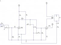
The input filter was most likely to compensate the frequency responce of the phono head so it wouldnt be needed here. The balance pot is fine if you add a 1meg resistor from the 50C5's grids to ground to ensure they have a ground connection should the pot go open.
Now looking at the voltages, the 50C5's are well within what would be expected,but, something is off with the 12AX7. If I read correctly your getting .6 volts at the cathode and 3.6 and 4 volts at the grids which is definitly not correct. If you have another 12AX7 try swapping them to see if things change dramatically, if not, then there may be an issue with grounding at the volume pot.
Now looking at the voltages, the 50C5's are well within what would be expected,but, something is off with the 12AX7. If I read correctly your getting .6 volts at the cathode and 3.6 and 4 volts at the grids which is definitly not correct. If you have another 12AX7 try swapping them to see if things change dramatically, if not, then there may be an issue with grounding at the volume pot.
The input filter was most likely to compensate the frequency responce of the phono head so it wouldnt be needed here. The balance pot is fine if you add a 1meg resistor from the 50C5's grids to ground to ensure they have a ground connection should the pot go open.
Now looking at the voltages, the 50C5's are well within what would be expected,but, something is off with the 12AX7. If I read correctly your getting .6 volts at the cathode and 3.6 and 4 volts at the grids which is definitly not correct. If you have another 12AX7 try swapping them to see if things change dramatically, if not, then there may be an issue with grounding at the volume pot.
I added teh bleeder resistors to teh balance pot... I will try to reduce teh value of teh new filter resistor, to raise the B+ ,,, it looks like teh voltage is low by about 8V to all the tubes.....
Sorry for the confusion, the chart didn't post teh way it looked on the preview,,,,
Here are the corrections,,,12AX7 cathode 6.6V each side,,,,,
GRID.....pin 2,,,, -.80 at volume off,, -4.00 at half volume,, -.80 full volume
GRID.....pin 7,,,, -.75 at volume off,,,-4.00 at half volume,, -1.1 full volume,,, the partial volume readings fluctuate as teh pot is rotated, and distortion gets worse as volume goes up...
Thanks for your help,
John
Last edited:
John,
The Zenith record player the amp came out of was cheap, LOFI, JUNK.
Are you willing to spend some money to get solid performance? A quite decent 2 WPC amp can be executed around a 12AX7 and 2X 50C5s. Per Paul Joppa's 102 dB. rule, critical listening, with that small amount of power, requires 99 dB. sensitive speakers. Can you borrow such equipment? Purchasing that sort of stuff is quite costly.
Edcor's model XSE15-8-2.5K O/P trafo will work for you, IF appropriate actions are taken. Don't be put off by the 70 Hz. low freq. limit. That 15 W. "iron" has the magnetic headroom needed to support a GNFB loop, which will yield acceptable bass extension. Among many, many, things, Zenith's OEM guano lacks magnetic headroom.
Thanks for the info....
I added teh bleeder resistors to teh balance pot... I will try to reduce teh value of teh new filter resistor, to raise the B+ ,,, it looks like teh voltage is low by about 8V to all the tubes.....
Sorry for the confusion, the chart didn't post teh way it looked on the preview,,,,
Here are the corrections,,,12AX7 cathode 6.6V each side,,,,,
GRID.....pin 2,,,, -.80 at volume off,, -4.00 at half volume,, -.80 full volume
GRID.....pin 7,,,, -.75 at volume off,,,-4.00 at half volume,, -1.1 full volume,,, the partial volume readings fluctuate as teh pot is rotated, and distortion gets worse as volume goes up...
Thanks for your help,
John
Correction... the 6.6v cathode is teh 50C5,,,,, teh 12AX7 Cathode is .63, both pins 3 & 8.....the plate of teh 50C5's is 114.5v ,, after i replaced teh filter resistor and installed a big cap..
Well neg. voltage on the grid is better than pos. as far as the tube's health is concerned,however, there should not be any change in voltage as the pot is rotated. Try removing the volume pot and using a fixed resistor divider, say two 220k, one from grid to ground and one from grid to input if your source doesnt have a volume control, otherwise just the one from grid to ground with input directly to grid if your source has a volume control. Also check to make sure your source has no dc at it's output as well.
Last edited:
If by source you mean tape deck/cd player,,, I just read the output jacks on the tape deck, and get -1to-4VDC, fluctuating... I may have a meter issue, its a DMM with a new battery,, but maybe I should try to get another one and confirm teh readings...
With teh filter mods, I find I can go higher in volume before distortion , so I'm moving in teh right direction...
Also, I noticed two 68K resistors that haven't been changed, (real hard to read on teh schem),,, They go from teh grid to teh volume wipers,,, seems like they are right where we're working...I don't have any 68K on hand, but, I have 100K or 56K, If you think either of those will work...If not, Ill pick some up....
Thanks,,John,
An inexpensive DMM can't yield correct info. about an AC signal. A true RMS meter, like a Fluke, is needed and they carry substantial price tags. As freq. rises, things can even dicier. An o'scope of considerable bandwidth may be needed.
I'm reading DC...
Are you playing music through while taking readings? This can account for flucuating readings from the source. I would also do the same here as with the balance pot since the same issue can occur. The 68k's are known as grid stoppers. They form a low pass filter with the tubes internal capacitance to stave off oscillations. I think 68k is higher than is necessary,although they may have been necessary with the original phono circuit, you can probably go as low as 1k without issue here. So what it seems to me now is that with the increase in B+ voltage your getting more out before distortion then most likely the amp is just running out of steam so to speak. Remember using an 8 ohm when the transformer wants a 4 ohm is reducing output by almost a 1/3 and nearly doubling the distortion.
After digging up some models I did some quick sims and found that for the most part changing coupling caps and cathode bypass caps had little effect on increasing bass with an output transformer with low primary inductance as yours most likely are. The only method which made a noticeable difference was a tuned feedback loop as I mentioned before. As a bonus, it not only increased bass but also cut distortion nearly in half. It is simply a capacitor and resistor in series from the output to the 12AX7 cathode, a fairly painless mod than can easily be removed again. Note 1 Getting the connection to the correct side of the secondary so the phase is correct or it will be positive feedback resulting in the the amp having way too much gain or squeeling or motoring noise. Note 2 The size of the capacitor changes the frequency which the bass boost starts to occur. The smaller the size the sooner the bass starts being boosted, going too small will start to make the amp sound boomy and too large it wiill have no effect. Attached is schematic with the feedback loop with starting values to start boosting bass at around 100hz. Removing the 47uF bypass caps was helpful in smoothing out the overall frequency and further reduced distortion.
Attachments
Hi J...
Well first of all, thanks for hanging in there with me,,,,
Yes, I am playing it while taking readings,,, thought I had to have a load on it,, speakers,, and an input,,, but, i don't know for sure... is it ok to run it with out an input?
I used to know ohms law, many years ago, but, if you think I can just test lead resistors in,,, that won't be a problem.. I have some, just not 68K,,, easy to get, tho....
Well, I guess tahts whats happening, its out of steam,,, I took out teh 100ohm filter, and worked my way down to 15ohm,,, teh smallest 5W i had...I also took out teh first stage cap (100-150 I think), and replaced it with a 440/200V that I had,,, think the distortion is pretty much gone, and some bass improvement...
I understand what you are saying about teh 4ohm output into teh 8ohm speakers, I saw teh tube specs sheet,,, 1.9w...I guess the only way to fix that is with a different OPT or different speakers...
The set of tubes in it are the originals,, and tehy tested the best,,,I have a couple other ax7's,, but they don't sound as good,,, no more output tubes, tho...
I have to say, this thing sounds surprisingly good,,,for an underpowered, 50 year old cheap design,,,
So, now I have a couple more questions... for teh balance pot, shall I just take 1M resistors from teh wiper to ground again? You mentioned going to a pair of 270K resistors for teh 50c5's,,, did you mean one on each channel, or a pair (2) on each channel? I already replaced teh 150's with 180's, but it didn't do much for teh bass...the other thing you mentioned was feed back loop,,,still a viable option??
This is my test mule,, I ran 6-8 cd,s thru it this afternoon,,, and it has a clean, natural sound.... the exercise was to learn some tube theory.... so, whats next??
Thanks again, I appreciate teh time you're taking...
Regards,
John
After digging up some models I did some quick sims and found that for the most part changing coupling caps and cathode bypass caps had little effect on increasing bass with an output transformer with low primary inductance as yours most likely are. The only method which made a noticeable difference was a tuned feedback loop as I mentioned before. As a bonus, it not only increased bass but also cut distortion nearly in half. It is simply a capacitor and resistor in series from the output to the 12AX7 cathode, a fairly painless mod than can easily be removed again. Note 1 Getting the connection to the correct side of the secondary so the phase is correct or it will be positive feedback resulting in the the amp having way too much gain or squeeling or motoring noise. Note 2 The size of the capacitor changes the frequency which the bass boost starts to occur. The smaller the size the sooner the bass starts being boosted, going too small will start to make the amp sound boomy and too large it wiill have no effect. Attached is schematic with the feedback loop with starting values to start boosting bass at around 100hz. Removing the 47uF bypass caps was helpful in smoothing out the overall frequency and further reduced distortion.
Guess we were typing at the same time,,, I didn't remove teh 47uF bypass caps, should I? they were suggested early on the rebuild....
After digging up some models I did some quick sims and found that for the most part changing coupling caps and cathode bypass caps had little effect on increasing bass with an output transformer with low primary inductance as yours most likely are. The only method which made a noticeable difference was a tuned feedback loop as I mentioned before. As a bonus, it not only increased bass but also cut distortion nearly in half. It is simply a capacitor and resistor in series from the output to the 12AX7 cathode, a fairly painless mod than can easily be removed again. Note 1 Getting the connection to the correct side of the secondary so the phase is correct or it will be positive feedback resulting in the the amp having way too much gain or squeeling or motoring noise. Note 2 The size of the capacitor changes the frequency which the bass boost starts to occur. The smaller the size the sooner the bass starts being boosted, going too small will start to make the amp sound boomy and too large it wiill have no effect. Attached is schematic with the feedback loop with starting values to start boosting bass at around 100hz. Removing the 47uF bypass caps was helpful in smoothing out the overall frequency and further reduced distortion.
I just looked at teh schem again,,, the plate is negative, so , teh blue wire on teh OPT's should be teh neg side,,, i guess thats where the feedback loop would go, if i dont want pos feedback.....Looks like all teh loop has to do, is connect teh OPT primary to teh secondary...
Last edited:
The 270k were an exercise to check if the volume pot had issues,but, I think the issue was playing music while taking measurements is all. What I also meant was to add the 1meg resistors to the 12AX7 grids like you did with 50C5's since the volume pot is their only path to ground and can go open as well. The 47uF's have an effect on frequency, making midbass and up more pronounced while the bottom end remains rolled off. There is plenty of gain to not use bypass caps on the 50C5's anyway. If your output transformers color coded like most then you have red/black primary and blue/black secondaries, so yea the feedback would be taken from blue. If you have the issues mentioned then simply swap to the black lead on the output side no biggie.
The 270k were an exercise to check if the volume pot had issues,but, I think the issue was playing music while taking measurements is all. What I also meant was to add the 1meg resistors to the 12AX7 grids like you did with 50C5's since the volume pot is their only path to ground and can go open as well. The 47uF's have an effect on frequency, making midbass and up more pronounced while the bottom end remains rolled off. There is plenty of gain to not use bypass caps on the 50C5's anyway. If your output transformers color coded like most then you have red/black primary and blue/black secondaries, so yea the feedback would be taken from blue. If you have the issues mentioned then simply swap to the black lead on the output side no biggie.
I think you mean to jump the balance pot, correct? Looks like teh volume is already grounded...
I'll remove the bypass caps, when i try the feedback,,,
The primaries are color coded, teh secondaries are just magnet wire... i can test for polarity....
Thanks for the info,,,
Had some time this afternoon, I replaced teh 68K's, removed teh bypass caps and put the 1M bleeders on teh grids...
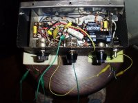
I have teh bypass loop clipped in,,, started with teh values on teh schematic, and have 2uF/2.2K running now,,, these sound pretty good, smooth transition between highs and lows...and, as you expected the distortion is nil... The grids read about 0v, and teh outputs 113.5-114v,,, so, it seems its pretty close to specs, even with all teh mods...
Heres a pic of the latest version,,, not much more room!!!
Attachments
I just looked at teh schem again,,, the plate is negative, so , teh blue wire on teh OPT's should be teh neg side,,, i guess thats where the feedback loop would go, if i dont want pos feedback......
Distortion is nil... that is nice to know you got this amp to where it ought to be.
And excellent job on following all the instructions that the tube amp experts here threw at you without too much guidance (I wouldn't have been able to tackle something like this over such a short span of time without many MS Paint hand drawn pictures and a step by step). These guys here are probably some of the best on the internet.
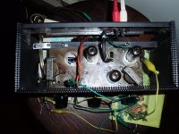
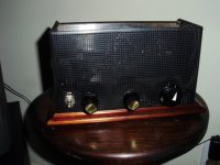
Three questions for you... are you going to leave this as is at this point? Now, only if it is easily accessed, what does the tube side of this 50 year old amp look like? And since you are bit by the tube bug, what is the next project going to be?
And excellent job on following all the instructions that the tube amp experts here threw at you without too much guidance (I wouldn't have been able to tackle something like this over such a short span of time without many MS Paint hand drawn pictures and a step by step). These guys here are probably some of the best on the internet.
Three questions for you... are you going to leave this as is at this point? Now, only if it is easily accessed, what does the tube side of this 50 year old amp look like? And since you are bit by the tube bug, what is the next project going to be?
Distortion is nil... that is nice to know you got this amp to where it ought to be.
And excellent job on following all the instructions that the tube amp experts here threw at you without too much guidance (I wouldn't have been able to tackle something like this over such a short span of time without many MS Paint hand drawn pictures and a step by step). These guys here are probably some of the best on the internet.
Three questions for you... are you going to leave this as is at this point? Now, only if it is easily accessed, what does the tube side of this 50 year old amp look like? And since you are bit by the tube bug, what is the next project going to be?
Thanks,,, The plan with this little amp, was to learn some tube theory... so, now taht its working,,,I learned how much I don't know!!!! Yep, I kinda got off to a rough start, but jerluwoo not only knows this stuff, but can explain it... makes all the difference...I didn't want a "paint by numbers" explanation. I blew up a couple caps, and a resistor or two along teh way, but that's part of teh learnin'
I don't think I can do much more with it, without starting over in a bigger chassis, with new transformers,,, I took a pic of teh top of it, I guess I post the bottom also, as it is now...
I found a schematic for a 5 tube amp built around 6V6 tubes, but the more I learn, it may not be a very efficient design...or maybe find an old magnaox console amp to play with, a lot more room in those chassis!!!
Thanks again for replying...
John
Attachments

- Status
- This old topic is closed. If you want to reopen this topic, contact a moderator using the "Report Post" button.
- Home
- Amplifiers
- Tubes / Valves
- rebuilding 3tube zenith amp