Pheonix 13 with new clamp overload recovery
Hello Edmond
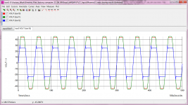
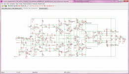
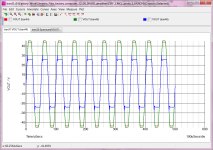
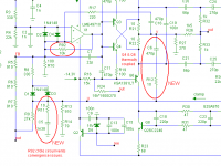
Here are the plots of the clamp in action with differing loads 2 (blue) ,4(red) and 8R(green). The circuit is attached and notice I had to set the zeners diode on the clamps to 5.6 Volts for the amp to work.
Regards
Arthur
Hello Edmond
Here are the plots of the clamp in action with differing loads 2 (blue) ,4(red) and 8R(green). The circuit is attached and notice I had to set the zeners diode on the clamps to 5.6 Volts for the amp to work.
Regards
Arthur
Attachments
Hi Arthur,
Good work! As for the zeners, I suppose D5/6, right?
What happens with 3V6 zeners?
Also, please check if very high frequency ringing is present during clipping and at various test points. If so, the amplitude might be very small.
Probably you have to increase the resolution in order to see it anyhow.
Cheers,
E.
Hi Arthur,
Good work! As for the zeners, I suppose D5/6, right?
What happens with 3V6 zeners?
Also, please check if very high frequency ringing is present during clipping and at various test points. If so, the amplitude might be very small.
Probably you have to increase the resolution in order to see it anyhow.
Cheers,
E.
Hello Edmond
D5/6 are the diodes I am taking about.
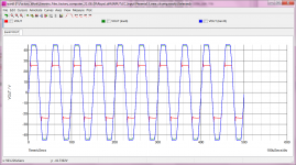
I changed the following simulator paramaters Relative tolerance to 1u and Voltage tolerance to 1n and with the everthing else being the same the following is what I get into 8R 4R and 2R.
The simulator shows no oscillations in the waveform.
Regards
Arthur
Attachments
Last edited:
Correction
Hello Edmond
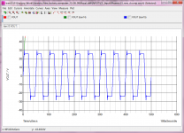
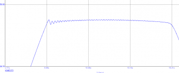
When I change the zeners to 3.6V the simulations seem to stop at about 8us for the 8R and 4R but 2R load runs fine because of ouput current limit protection. See attached graph.
Regards
Arthur
Hello Edmond
When I change the zeners to 3.6V the simulations seem to stop at about 8us for the 8R and 4R but 2R load runs fine because of ouput current limit protection. See attached graph.
Regards
Arthur
Attachments
Last edited:
D5/6 zener voltage 5.6V
Hello Edmond
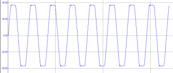
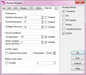
Finally I tightened even further the following simulator paramaters Relative tolerance to 10n and Voltage tolerance to 1p and with the everthing else being the same the following is what I get into 8R 4R and 2R, interestingly I also stepped the zeners D5/6 from 3.6V up until the simulations did not slow down due to low level oscillations and the zener voltage that does this is 5.6V.
Regards
Arthur
Hello Edmond
Finally I tightened even further the following simulator paramaters Relative tolerance to 10n and Voltage tolerance to 1p and with the everthing else being the same the following is what I get into 8R 4R and 2R, interestingly I also stepped the zeners D5/6 from 3.6V up until the simulations did not slow down due to low level oscillations and the zener voltage that does this is 5.6V.
Regards
Arthur
Attachments
Magified Clamp
Hello Edmond
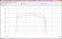
Here is the zoomed clamp response for 8R and 4R , these sims are done with the following Sim options (attached). The input voltage is 3Vp
Interestingly the 4R load causes the some issues and the zener voltage D5/6 needed for the circuit to converge needs to be raised to 6.2V. These issues are only shown up when I tighten up the previous mentioned sim setting .
Regards
Arthur
Hello Edmond
Here is the zoomed clamp response for 8R and 4R , these sims are done with the following Sim options (attached). The input voltage is 3Vp
Interestingly the 4R load causes the some issues and the zener voltage D5/6 needed for the circuit to converge needs to be raised to 6.2V. These issues are only shown up when I tighten up the previous mentioned sim setting .
Regards
Arthur
Attachments
Are they 22r base stoppers on the outputs and yet, only 10r on the drivers?
Why did you choose that high?
Hello Andrew
How I end up with 22R is that in another amp I built I found I had a low level oscillation at high frequencies and increasing this value at the time seemed to solved the problem, but I must say just recently I discovered that the source of the problem really was caused by the front end diff pair. This amp works fine with 4.7R now.
Regards
Arthur
Hello Edmond
Here is the zoomed clamp response for 8R and 4R , these sims are done with the following Sim options (attached). The input voltage is 3Vp
Interestingly the 4R load causes the some issues and the zener voltage D5/6 needed for the circuit to converge needs to be raised to 6.2V. These issues are only shown up when I tighten up the previous mentioned sim setting .
Regards
Arthur
Hi Arthur,
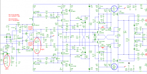
I wonder whether in real life D5/6 will also cause some issues. I finally found a way to circumvent convergence troubles: simply limit the gain of the op-amp by tying 10kOhm between output and inverting input. (At HF this temporary resistor has little effect)
Now I can go on with analysing the new clamp compensation. I think that bringing down the ULGF from 8.3 to 1.5MHz is a 'real asset'.
Cheers,
E.
Attachments
Hello Edmond
...............
The new clamp seems to give an improvement in phase margin and it also reduces the unity cross over frequency point to 1.5Mhz.
Regards
Arthur
Hi Arthur,
Depending on the position of the gain probe, I got an ULGF of 3; 4 and 7.8MHz respectively. So, where did you put the gain probe?
Cheers,
E.
pitfall
Hi Arthur,
Putting the probe at that position, I get PM = 99 deg. @ 3MHz. IOW, my ULGF is two times as high as yours. The reason for this huge difference is that you are trapped in a pitfall, which also happened to me, btw.
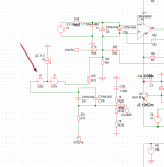
With a DC voltage as input signal, the bootstrap caps (C23/24, 22uF) don't work as intended. As a result, the driver of the OPS is heavily under-biased. Hence a much lower gain. If you replace these caps by voltage sources (22.5V), you will get a more realistic result.
BTW, with the old compensation I get PM = 31 deg. @ 8MHz. So the new one is a huge improvement.
Cheers,
E.
Hi Arthur,
Putting the probe at that position, I get PM = 99 deg. @ 3MHz. IOW, my ULGF is two times as high as yours. The reason for this huge difference is that you are trapped in a pitfall, which also happened to me, btw.
With a DC voltage as input signal, the bootstrap caps (C23/24, 22uF) don't work as intended. As a result, the driver of the OPS is heavily under-biased. Hence a much lower gain. If you replace these caps by voltage sources (22.5V), you will get a more realistic result.
BTW, with the old compensation I get PM = 31 deg. @ 8MHz. So the new one is a huge improvement.
Cheers,
E.
Hello Edmond
")
Clamp
Hello Edmond
Sorry for the previous mail , I became distracted andI got timed out before I could correct it.
Yes indeed the new compensation on the clamp circuit is much improved , do you think you could post your microcap schematic
Do you think that this new compensation can be applied to different circuits I applied this clamp with old style compensation on an amp I run you are familiar with diff with EC output do you think it could be applied there. I will send PM
Regards
Arthur
ULG and Phase margin
Hello Edmond
With the votage sources as you have shown I can only get a negative extreme ULG is 2.98MHz and 97 degree PM and the ULG an PM.
For the postive extreme as the output of the amp is 2.53Mhz and 84degrees PM , but the negative voltage source must be put to zero volts to get a positive voltage out, is this what you have to do.
I find that with these voltage sources in the circuit that the input voltage does not determin what the ouput voltage is, is this what you find
Regards
Arthur
Last edited:
clamp reponse
Hmmm....weird.
The amp should work (read: simulate) just as good with voltage sources or with caps.
When Vi = +2.5V I got PM = 98.3 deg. @ 3MHz; GM1 = 22dB @ 18MHz and GM2 = 34dB @ 95MHz.
When Vi = -2.5V I got PM = 97.5 deg. @ 2.6MHz; GM1 = 22dB @ 18.7MHz and GM2 = 34dB @ 94MHz.
Yes indeed, two GM's, because of the gain dip @ 25MHz and subsequent phase wobble, which resulted in two (sometimes three) zero phase intercept points.
(see the graphs at: http://www.diyaudio.com/forums/solid-state/174218-rebirth-phoenix-12.html#post2547088)
Cheers,
E.
Pit full Post
Hello Edmond
In post 137 what is the output load on the amplifier when you are doing the testing of the clamps stability.
Also the amp you are simulating with is it with the Sanken outputs is it a big deal to do it with the TT Onsemi output circuit.
Regards
Arthur
Hello Edmond
In post 137 what is the output load on the amplifier when you are doing the testing of the clamps stability.
Also the amp you are simulating with is it with the Sanken outputs is it a big deal to do it with the TT Onsemi output circuit.
Regards
Arthur
Last edited:
- Status
- This old topic is closed. If you want to reopen this topic, contact a moderator using the "Report Post" button.
- Home
- Amplifiers
- Solid State
- Rebirth of the Phoenix