Hi Arthur,
The development of the enhanced clamps gets very slowly. The results of a highly simplified version contradict the results of the full fledged version. Rather confusing, I would say. Furthermore, I have those pesky convergence errors, which make things extreme time-consuming. Then we have the debate on TMC vs TPC and the troubles with Olivier's amp, two more sources of delay. Let's hope that New Year may bring more progress in the development of the clamps.
Cheers,
E.
Convergence stuff
Hello Edmond
Sometimes I enter a circuit in different simulator just in case the circuit is good and simulator cannot converge. If this would help in any way but don't feel obligated I would be glad to test your clamp circuit in the simetrix simulator which has very powerfull convergence , please note I think MC9 is very good and it just might be as good as simetrix.
Regards
Arthur
I use simetrix, and i can only aknowledege how much it is user friendly
but the free version has fairly limited node number..
Somewhat mandatory to design for the best perf/compexity ratio...
Hello Edmond
Sometimes I enter a circuit in different simulator just in case the circuit is good and simulator cannot converge. If this would help in any way but don't feel obligated I would be glad to test your clamp circuit in the simetrix simulator which has very powerfull convergence , please note I think MC9 is very good and it just might be as good as simetrix.
Regards
Arthur
Hi Arthur,
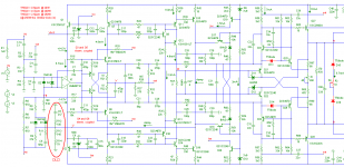
Here are (finally) the schematics of the old and the new clamp frequency compensation. The zip file contains the complete schematics in MC9 format.
The idea behind it is that, when the clamp kicks in and thus D1 or D3 is conducting, capacitor C6 is effectively paralleled to C16. As a result, the HF loop-gain* is halved and the clamp should be more stable, at least that's the intention.
If it's really more stable has to be figured out by extensive simulations of the loop at several location. Regrettably, those pesky convergence issues spoil the whole affair. I hope simetrix do better,
Cheers,
E.
Attachments
Last edited:
Simetrix Simulation results
Hello Edmond
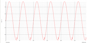
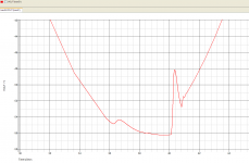
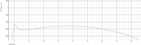
Thanks for the info, here are the results from simetrix, bearing in mind that the input voltage is 1.4142136 RMS (2V peak) and the load is 8R with a single of output devices.
The graphs show us what happens as the clamp is just starting to be used. Interestingly the problem with the clamp is always with the extreme negative voltage out even with old and new clamp circuitry. I show also the negative and positive voltage recovery.
Regards
Hello Edmond
Thanks for the info, here are the results from simetrix, bearing in mind that the input voltage is 1.4142136 RMS (2V peak) and the load is 8R with a single of output devices.
The graphs show us what happens as the clamp is just starting to be used. Interestingly the problem with the clamp is always with the extreme negative voltage out even with old and new clamp circuitry. I show also the negative and positive voltage recovery.
Regards
Attachments
Last edited:
Clamp
Hi Arthur,
It seems to me that the neg. clamp doesn't work at all. Are these figures from the old or the new clamp (or both?). Did you check the Vce's of the VAS (Q12 & 13) and the drivers (Q27 & Q28)? They should never fall below 0.6V respectively 1V.
BTW, apparently you have increase the supply voltages. This doesn't ease a direct comparison. Debugging a design only makes sense if we are using exactly the same schematic.
Cheers,
E.
VAS Q13 VCE
Hello Edmond
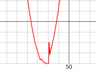
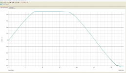
I have adjusted power supply voltages to +/-50V.
The Vce on your circuit Q13 (Q15 my circuit) drops below 0.6V it goes to 2mV see attached files. This is on the new clamp circuit.
Will post on old clamp circuit Q13.
Regards
Arthur
Hello Edmond
I have adjusted power supply voltages to +/-50V.
The Vce on your circuit Q13 (Q15 my circuit) drops below 0.6V it goes to 2mV see attached files. This is on the new clamp circuit.
Will post on old clamp circuit Q13.
Regards
Arthur
Attachments
Hi Arthur,
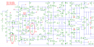
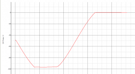
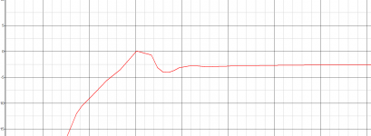
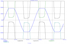
Here's the schematic of the Sanken version + clipping at 20kHz, Vi=2Vpk and Vcc = 50V.
Blue=Vout
black=Vce-VAS x 10
green = Vce-driver x 10
edit1: As you see, none of them saturate.")
edit2: Walter (aka Waly, aka YWN), neither questions, nor comments, please!
Cheers,
E.
Here's the schematic of the Sanken version + clipping at 20kHz, Vi=2Vpk and Vcc = 50V.
Blue=Vout
black=Vce-VAS x 10
green = Vce-driver x 10
edit1: As you see, none of them saturate.
edit2: Walter (aka Waly, aka YWN), neither questions, nor comments, please!
Cheers,
E.
Attachments
Last edited:
Schematic Problem solved
Hello Edmond
I found the error, I had a connection mistake in the negative rail clamp in Phoenix13 (MC9 ref) Q18 the emitter was connected to the 3.9V zener were the Q18 base needed to be connected to the zener.
Just one further thing , the original Phoenix13 circuit converges when you reduce C31 to 1pf in MC9 , do you consider this a problem removing this cap.
Arthur
convergence errors
> Just one further thing , the original Phoenix13 circuit converges when you reduce C31 to 1pf in MC9 ,
> do you consider this a problem removing this cap.
Hi Arthur,
Hard to say at the moment. It's a speed-up cap. Removing it might affect the step response.
I also tried 1pF, but to no avail. In your case, it was just a coincidence. For the same reason, changing another component (or increasing/decreasing Vcc by 0.1V) will sometimes cure the convergence troubles. It's a mathematical issue (resolving a large matrix), not a electronics one. Sometimes, I even get convergence errors, after renaming the components!
Cheers,
E.
Clamp stuff
Hello Edmond
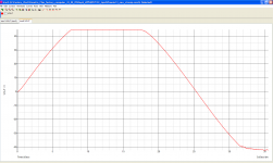
I simulated Phoenix13 with standard clamp and new clamp mod into 4ohm load 2Vrms in. Attached are the graphs or performance, as can be seen neither clamp is stable when the voltage is clipping on the negative going voltage waveform.
Regards
Arthur
Hello Edmond
I simulated Phoenix13 with standard clamp and new clamp mod into 4ohm load 2Vrms in. Attached are the graphs or performance, as can be seen neither clamp is stable when the voltage is clipping on the negative going voltage waveform.
Regards
Arthur
Attachments
Hello Edmond
I simulated Phoenix13 with standard clamp and new clamp mod into 4ohm load 2Vrms in. Attached are the graphs or performance, as can be seen neither clamp is stable when the voltage is clipping on the negative going voltage waveform.
Regards
Arthur
Hello Guys
I recently rechecked the Pheonix 13 with new clamp and found a mistake in my circuit Q28 on attached schematic should be KSA1220 and not whats shown on the posted schematic.
Will attached corrected schematics shortly including phase margin of feedback clamps.
Regards
Arthur
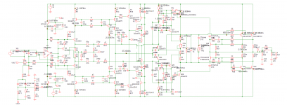
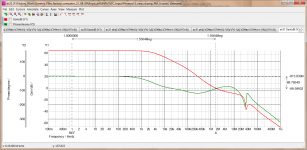
Pheonix 13 circuit and clamp
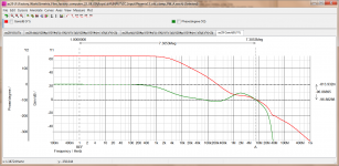
Hello Edmond
Both the old and new clamp work in the Phoenix 13 amplifier. For the old clamp the 0dB frequency is 8.268MHz and the phase margin is about 89 degrees and for the new clamp the 0dB frequency is 1.509Mhz and the phase marging is about 95 degrees.
The new clamp seems to give an improvement in phase margin and it also reduces the unity cross over frequency point to 1.5Mhz.
Regards
Arthur
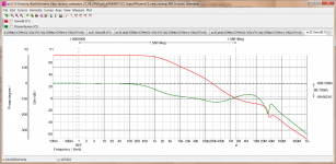
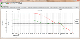
Loop Gain Plots of active clamps
Hello Edmond
Attached are the Loop Gain plots of the of Pheoenix13 with old and new clamps .The new clamp method has greater phase margin in both the negative and positive extremes 92 degrees as oposed to 84 degrees.
Regards
Arthur
Hello Edmond
Attached are the Loop Gain plots of the of Pheoenix13 with old and new clamps .The new clamp method has greater phase margin in both the negative and positive extremes 92 degrees as oposed to 84 degrees.
Regards
Arthur
Attachments
- Status
- This old topic is closed. If you want to reopen this topic, contact a moderator using the "Report Post" button.
- Home
- Amplifiers
- Solid State
- Rebirth of the Phoenix