neutron7 said:what does anyone think of that?
Hi Neutron,
I actually have been fiddling with the idea. Here is my take on the situation. I think that the PGA chips while being superb for what they are, actually will dominate the sound of anything coming after them. In essence they are a ladder attenuator in front of a 2134(or equivalent) opamp. The opamp is always on, the signal always passes through it.
I would take an approach with the AD815 where I use the Joshua Tree attenuator directly in front of the AD815 preamp. This has several advantages over the PGA:
1) I can set the attenuation range to whatever I like (0 - -63.5db or 0 - 95.5 db, etc...) simply by computing the resistors as I like.
2) The output impedance from the JT is constant so I can more easily control the offset of the AD815 with a Carlos type nulling circuit.
3) The AD815 preamp can actually be made small enough to easily mount above the JT relay PCB, so you could stack them for very short low signal runs.
4) no active circuit in the mix except the AD815.
I have tried the AD815 in the past as Carlos built, but have not played with it much for quite a long time. I will redesign the layout a bit to fit over the JT. That should be very easy.
I will keep you posted.
Cheers!
Russ
neutron7 said:that sounds like a good idea. Does the Joshua tree have a constant output resistance? its easier to make the AD behave if it does.
See point #2
")
Yes, the output impedance of the JT is constant, which is a big win for devices where input offset can be an issue.
Cheers!

Russ
Re: Sounds great.
Hi George, well the math works out like this:
For output impedances of <=25K and attenuation into a 100K load you will get approximatly LZin = 2.5 x Zout where LZin is the lowest Zin. The highest Zin is Zload + Zout. So for your case the lowest Zin would be a bit more than 60K and the highest would be around 125K.
The value you have chosen seems too high to me and would require some very large value resistors. I would go much lower. I intend to use something like 1.5K or 750R output impedance which gives a LZin of about 3.7K or 1.8K which should be a very easy load for most sources. If you utilize good .6W resistors like the Pheonix metal film resistors you could easily even go lower than that. Say 500ohms output impedance.
I am using 750R output impedance with my XBOSOZ with the attenuator on the preamp's output.
Cheers!
Russ
Panelhead said:For a 25K unit, about how much does input impedance vary?
George
Hi George, well the math works out like this:
For output impedances of <=25K and attenuation into a 100K load you will get approximatly LZin = 2.5 x Zout where LZin is the lowest Zin. The highest Zin is Zload + Zout. So for your case the lowest Zin would be a bit more than 60K and the highest would be around 125K.
The value you have chosen seems too high to me and would require some very large value resistors. I would go much lower. I intend to use something like 1.5K or 750R output impedance which gives a LZin of about 3.7K or 1.8K which should be a very easy load for most sources. If you utilize good .6W resistors like the Pheonix metal film resistors you could easily even go lower than that. Say 500ohms output impedance.
I am using 750R output impedance with my XBOSOZ with the attenuator on the preamp's output.
Cheers!
Russ
Here is the output from my calcution program for 750R output impedance:
low Zin:1857.0934352444326
Interstage Impedance=750.0 ohms
Target Load=100000.0 ohms
Attenuation per step=-0.5db.
Number of stages=7
stage:1 r1:787 r2:15,800 r3:0
stage:2 r1:90.9 r2:0 r3:6,810
stage:3 r1:196 r2:0 r3:3,650
stage:4 r1:442 r2:0 r3:2,050
stage:5 r1:1,130 r2:0 r3:1,240
stage:6 r1:4,020 r2:0 r3:909
stage:7 r1:29,400 r2:0 r3:768
stage db zOut zIn
1 -63.45 748.93 1857.09
2 -63.03 748.93 1897.49
3 -62.45 748.93 1946.31
4 -62.02 748.93 2000.77
5 -61.44 748.93 1996.24
6 -61.02 748.93 2059.12
7 -60.44 748.93 2143.69
8 -60.02 748.93 2233.79
9 -59.46 748.93 2026.35
10 -59.04 748.93 2094.5
11 -58.45 748.93 2187.69
12 -58.03 748.93 2286.6
13 -57.45 748.93 2327.9
14 -57.03 748.93 2457.08
15 -56.45 748.93 2655.94
16 -56.02 748.93 2869.33
17 -55.43 748.93 1970.78
18 -55.01 748.93 2029.31
19 -54.43 748.93 2106.84
20 -54.01 748.93 2189.8
21 -53.43 748.93 2214.1
22 -53.01 748.93 2318.46
23 -52.42 748.93 2473.1
24 -52 748.93 2637.19
25 -51.45 748.93 2405.85
26 -51.02 748.93 2553.31
27 -50.44 748.93 2785.78
28 -50.02 748.93 3037.91
29 -49.45 748.93 3266.71
30 -49.02 748.93 3690.99
31 -48.44 748.93 4528.5
32 -48.01 748.93 5652.07
33 -47.53 748.92 1871.46
34 -47.11 748.92 1914.04
35 -46.53 748.92 1966.25
36 -46.11 748.92 2024.02
37 -45.53 748.92 2022.74
38 -45.11 748.92 2090.25
39 -44.52 748.92 2182.39
40 -44.1 748.92 2280.22
41 -43.54 748.92 2069.84
42 -43.12 748.92 2145.86
43 -42.54 748.92 2252.08
44 -42.11 748.92 2364.47
45 -41.54 748.92 2420.57
46 -41.12 748.92 2571.61
47 -40.53 748.92 2810.75
48 -40.11 748.92 3070.69
49 -39.51 748.93 2078.11
50 -39.09 748.93 2155.66
51 -38.51 748.93 2264.44
52 -38.08 748.93 2379.5
53 -37.51 748.92 2438.58
54 -37.09 748.92 2594.03
55 -36.5 748.93 2841.47
56 -36.08 748.93 3111.2
57 -35.53 748.92 2856.7
58 -35.11 748.92 3131.35
59 -34.52 748.92 3620.03
60 -34.1 748.92 4201.64
61 -33.53 748.92 4946.9
62 -33.11 748.92 6396.21
63 -32.52 748.92 11155.57
64 -32.1 748.92 30911.81
65 -31.35 763.45 1857.15
66 -30.93 763.45 1897.56
67 -30.34 763.45 1946.39
68 -29.92 763.45 2000.86
69 -29.34 763.44 1996.35
70 -28.92 763.44 2059.24
71 -28.34 763.44 2143.84
72 -27.92 763.44 2233.97
73 -27.36 763.43 2026.52
74 -26.93 763.43 2094.7
75 -26.35 763.43 2187.94
76 -25.93 763.43 2286.9
77 -25.35 763.42 2328.26
78 -24.93 763.42 2457.51
79 -24.35 763.43 2656.52
80 -23.92 763.43 2870.08
81 -23.33 763.6 1971.18
82 -22.91 763.6 2029.79
83 -22.33 763.61 2107.43
84 -21.91 763.61 2190.5
85 -21.33 763.58 2214.91
86 -20.91 763.58 2319.44
87 -20.32 763.59 2474.38
88 -19.9 763.59 2638.79
89 -19.35 763.51 2407.36
90 -18.92 763.51 2555.18
91 -18.34 763.53 2788.33
92 -17.92 763.53 3041.26
93 -17.34 763.46 3271.12
94 -16.92 763.46 3697.2
95 -16.34 763.49 4539.21
96 -15.91 763.49 5670.47
97 -15.44 747.78 1873.71
98 -15.02 747.78 1916.63
99 -14.43 747.84 1969.38
100 -14.01 747.84 2027.68
101 -13.43 747.66 2026.91
102 -13.01 747.66 2095.16
103 -12.43 747.75 2188.51
104 -12 747.75 2287.59
105 -11.45 747.2 2076.74
106 -11.02 747.2 2154.04
107 -10.44 747.35 2262.4
108 -10.02 747.35 2377.02
109 -9.44 746.9 2435.61
110 -9.02 746.9 2590.32
111 -8.44 747.13 2836.38
112 -8.01 747.13 3104.47
113 -7.41 753.79 2095.82
114 -6.99 753.79 2176.69
115 -6.41 754.16 2291.04
116 -5.99 754.16 2411.94
117 -5.41 753.02 2477.56
118 -4.99 753.02 2642.78
119 -4.4 753.6 2908.71
120 -3.98 753.6 3200.48
121 -3.43 750.15 2942.23
122 -3.01 750.15 3245.31
123 -2.42 751.07 3796.41
124 -2 751.07 4467.13
125 -1.43 748.21 5375.64
126 -1.01 748.21 7216.37
127 -0.42 749.66 14431.21
128 0 749.66 100749.66
Did not understand
Most my sources are cap coupled, the 3 - 4K is a bit low, I really prefer an input impedance in the 15 -25K range. Setting this unit up for an ouput impedance of 3 - 5K would get it up to where a 10 ufd cap should not cause any issue if used on the input.
For use on the output, this looks great. I have never tried using an attenuator on the output. I can see where getting full signal to the linestage circuitry has its advantages. If NP believes that is how it should be done, the idea has to have a lot of merit.
What is your planned time frame for the Joshua Tree log attenuator?
George
Well I have the pre-production PCBs in my hands and several prototypes built. The final PCBs (I found a couple minor flaws I wanted fixed prior to production) should be here Monday or Tuesday.
I am working on getting the resistor calc program up as a web application so people can compute custom resistor values. For now we are offering a 750ohm output impedance kit which suites the XBOSOZ with 10-22uf output cap perfectly. You can also order PCBs only if you like.
If you would like to have a list of resistors for some other minimum input impedance or output impedance contact me by email and I will email a resistor BOM back for you.
EDIT:
It sounds like a 5-6K output impedance would suite your needs well.
Cheers!
Russ
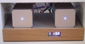
Hi just a quick note to say that i finally finished my preamp based on Carlos and Rudis work with the AD815.
Seeing as after initial testing i thought that the design was a keeper i spent a bit of time sorting out the casework and remote control setup.
It uses a remote control resistor ladder design and has also 4 remote controlled inputs all using relays. Great bit of kit from diyclub.biz.
I am loving it, here is the near finished unit (needs some smoked glass for the led window).
It sounds stunning and even the missues seems to approve, cant get better than that. My LM3886 chip amps are on top, to be honest i found they sounded better with them than the AMP3.
Needs more experiments however for the time being i am very happy.
(Did make the preamp modular though so different preamp moudles can be slotted in
Thanks for all the help guys Rudi in particular with your excellent pcb layouts.
Phil
Attachments
Hi Phil, top job mate
Is your only vol control via remote? Does that kit allow a pot or encoder to work also?
I'm guessing thats the v03 soshin kit. I wish there was more info on their website; seems interesting.
I got my 815 pre working a week or so back. Initially had dc problems; turned out I had a duff opa2134 in the servo
Spent ages trying to debug and tried the opamp last. Wotta plonker, should have done that first- thats what sockets are for!
Sounds great, and the servo takes care of all my dodgy sources
Hey float,
Yeah thats the one, I alos bough a 3310 to stick in one for the father in law, easy good enough for him.
I have tried diyclub stuff before, the documentation is usually nonexistant and the after sales something of a joke, the postage cost huge apart from that the lite audio board semm generally of a very high standard. The whole units work very well and looks pretty slick.
There is a option to put input and voulme button on the front but i quite like it ultra minimal like it is to be honest.
Yeah its a good sounding setup very happy, wethere I leave it be or keep tweaking cant tell at the moment. I awas thinking of doing a AWSR version but i need to get hold of some first or maybe a dual reg version. We'll see i love the setup but i like making the sutff more,
phil
The amp chassis came from conrad in europe. Couldnt find then on the english site but i ordered from germany. They were about 16 euros a peices, i have used then a lot for preamp, psu, they also do a half height that i have built an AMP3 and rehoused/tweak a SI in.
Lovely cases, thought the normal screw make then look cheap, i just ordered some hex bolts and they look much better.
The pre-amp chassis is a old network switch box gutted and with a piece of american oak as a face plate which my Dad cut and routered out the hole for me. Used a bit of Linseed oil to bring out the colour in the wood.
Pre-amp upgrades
FWIW, I converted my attenuator (DACT) to shunt mod (trivial mod: Disconnect the lead to the input of the pot, connect a 10-20k resistor in series with the input lead, and connect the resistor to the output of the volume pot). The end result is that the signal runs from the input jack through a 10-20k resistor to the output pin of the volume pot and that "unwanted signal " is shunted to ground. So the path is much shorter and does not have all those resistors in the path and also, you can buy the most exotic resistor for the 10k-20k.
And the result of this? So far, small details, especially in the mids, that were previously hinted at, are now much clearer and I also perceive more air in the highs. I'll report more as it unfolds....

Its been awhile since I've read the entire thead, so forgive me if this has been said.
I wonder if anyone has successfully used the AD815 for a preamp without the input voltage going to the NI input to null the DC offest. I'd like to build as simple as possible but at the same time not comprimise the sound. Would all that would be required be an output cap on the pre or an input cap on the amp?
Also with regards to the amount of voltage going to the NI input, is it just set-it-and-forget-it? And is it a matter of just applying 0 voltage to the input while measuring the DC offset at output and adjusting the trimmers until the offset is 0?
DC Dave said:Would all that would be required be an output cap on the pre or an input cap on the amp?
Yes
DC Dave said:
Also with regards to the amount of voltage going to the NI input, is it just set-it-and-forget-it? And is it a matter of just applying 0 voltage to the input while measuring the DC offset at output and adjusting the trimmers until the offset is 0?
You set it for 0 offset at your normal listening level(pot position). That is where you will have 0 offset but not in any position
Mine works better now
Did a little work on the grounding paths. I now measure the input offset instead of output. But they are directly related.
After a lot of diddling, the input now only goes up to 0.1 mv, with pots fully open. Used to go up to 2 mv.
I think you are okay if you have input and output caps and no nulling circuit. I measured one once with the nulling disconnected., seems the maximum output offset was around 80 mv or so.
George
- Status
- This old topic is closed. If you want to reopen this topic, contact a moderator using the "Report Post" button.
- Home
- Amplifiers
- Chip Amps
- (re)searching for a better preamp