
Quicksilver KT88 Schematic
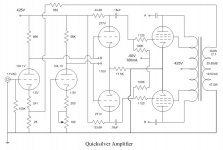
There were definitely some circuit drawing errors in the previous PDF file. I have corrected them and here is the result. The pink rectangular things referred to are probably the mica caps reffered to earlier. The exact wiring around the bias jack is probably not quite right, but it is close enough to get the idea. The source file is in Microsoft Visio. I will send it to you if you want it. Contact me at yahzdi@pointroberts.net.
There were definitely some circuit drawing errors in the previous PDF file. I have corrected them and here is the result. The pink rectangular things referred to are probably the mica caps reffered to earlier. The exact wiring around the bias jack is probably not quite right, but it is close enough to get the idea. The source file is in Microsoft Visio. I will send it to you if you want it. Contact me at yahzdi@pointroberts.net.
Attachments
Quicksilver KT88 schematic
Now I know this is a really old thread, but I would appreciate suggestions for tweaking these amps. Currently I am planning on replacing the .27uf coupling caps with .22 and .047 multicap RTXs in parallel. Also replacing the input bridge resistors with Vishay S102s (at $24 each), and the R15 and R16 signal path resistors with Kiwame 2 watt carbon film resistors. I am putting Vampire CMF2/OFC RCA jacks in and wiring the new connectors with silver wire. Most of these ideas came from this thread. Comments please. Thanks.
Now I know this is a really old thread, but I would appreciate suggestions for tweaking these amps. Currently I am planning on replacing the .27uf coupling caps with .22 and .047 multicap RTXs in parallel. Also replacing the input bridge resistors with Vishay S102s (at $24 each), and the R15 and R16 signal path resistors with Kiwame 2 watt carbon film resistors. I am putting Vampire CMF2/OFC RCA jacks in and wiring the new connectors with silver wire. Most of these ideas came from this thread. Comments please. Thanks.
Hi,
OMG, this thread is old....
IMHO the QS are still a great sounding tube amps.
All the tubes are still manufactured so there's no problem running one for years to come.
Ciao,")
This thread is old and no one has corrected the schematic of the KT88 that has been posted.
No phase inverter
I'm not quite sure how the above circuit works with regard to the second tube. Its grid is grounded and its cathode is not connected to the first tube's, thus it cannot either receive an input signal nor track the input signal received by the first tube. Effectively there is no phase inversion to the remaining push pull stages.
I'm not quite sure how the above circuit works with regard to the second tube. Its grid is grounded and its cathode is not connected to the first tube's, thus it cannot either receive an input signal nor track the input signal received by the first tube. Effectively there is no phase inversion to the remaining push pull stages.
Was it drawn by a drunken sailor? It is the worst looking schematic I have seen in a long time, using Visio too, what a waste of time...This thread is old and no one has corrected the schematic of the KT88 that has been posted.
It works just fine, of course, it would be better if QS just made it a balanced input stage to begin with.I'm not quite sure how the above circuit works with regard to the second tube. Its grid is grounded and its cathode is not connected to the first tube's, thus it cannot either receive an input signal nor track the input signal received by the first tube. Effectively there is no phase inversion to the remaining push pull stages.
The first tube is a voltage amplifier, directly coupled to the driver. The second tube holds the grid of the differential driver above ground, at the same static voltage as the other phase of the differential driver. The driver does the phase splitting since the current through the 17.5K cathode resistor must remain constant. This results in near perfect balance of the signal to the output tubes. That's part of the elegance of Peter's design. instead of crude potentiometers to hold balance, the circuit itself compensates for many forms of imbalance at the most critical location - just before driving the output tubes. Actually very ingenious. I have had a pair and they still can hold their own against any other design, even the overly complicated ARC designs IMHO. The other part of his excellent amps is the very well constructed output transformers, and solidly built power supply.
Post #110 is the best schematic for that version of the amp. Everything is there except the value of the capacitors on the plates of the output tubes and the power supply. I've never seen a value for those caps but I do know they were the old "domino" style mica capacitors so they must be in the pf range. Also the heater voltage is all 12.6VAC, the output tube heaters are in series and the other two tubes are 12FQ7s. A 6.3VAC heater supply would work also just wire the outputs in parallel and use 6FQ7s for the little ones for a DIY amp.
Craig
Craig
I have a question concerning the 8417 version of the Quicksilver. The schematic appeared in Post #15 on page 2 of this thread. It uses a 12AX7 input stage direct-coupled to a 12AU7 split-load inverter/driver stage. My question is whether Quicksilver used only half of each X7/U7 tube or did they tie both sections of each tube in parallel. Does anyone know?
- Status
- This old topic is closed. If you want to reopen this topic, contact a moderator using the "Report Post" button.
- Home
- Amplifiers
- Tubes / Valves
- Quicksilver KT88 mono 60watt amp schematic