???
Hi Mitch,
I can't even find hexfreds on Ixys site.
Any more detail on where and how you would insert these?
I can't see how these diodes are going to help anything but I keep an open mind.
Maybe you could use the circuitdaigram on pege to of this thread as a basis for your indication.
Thanx,")
Hi Mitch,
BTW a very good tweak is putting IXYS hexFreds in various places on the rails.
I can't even find hexfreds on Ixys site.
Any more detail on where and how you would insert these?
I can't see how these diodes are going to help anything but I keep an open mind.
Maybe you could use the circuitdaigram on pege to of this thread as a basis for your indication.
Thanx,
TYPOS AGAIN
Hi,
Maybe you could use the circuitdiagram on page two of this thread as a basis for your indications.
Cheers,
Hi,
Maybe you could use the circuitdaigram on pege to of this thread as a basis for your indication.
Maybe you could use the circuitdiagram on page two of this thread as a basis for your indications.
Cheers,
Quicksilver Mods
It would go in-between the 330uf cap and the choke in the pi filter, on the LINE side of the choke.
If there is another Choke that feeds the OPT, before that one as well.
They help keep things stable when the tubes are looking for more current from the front end.
There are other places it can be used !!!
IXYS part is DSEI12-12A
IXYS DSEI12-12A
I also have DSEI08-06A??? Not sure why I have these.
DSEI08-06A
Digi-Key part #
Mystery part??????
Ok....
It has C
MP930
500
1%
E
The part is air hung(floating) one side of the two leads is attached to the 8ohm output terminal and the other lead goes thru a resistor to ground, at the point where it hits the resistor it also goes thru a resistor to the cathode (pin 3) of the input tube.
Scratching my head and reaching for a bottle of JD.
Joe
CADDOCK SHEETS
Hi Joe,
Look here:
http://www.caddock.com/Online_catalog/Mrktg_Lit/MP9000_Series.pdf
Cheers,
Hi Joe,
Look here:
http://www.caddock.com/Online_catalog/Mrktg_Lit/MP9000_Series.pdf
Cheers,
NFB
Hi Joe,
It is most likely the feedback R from what you described.
Errr...not in the schematics I've seen..what do you mean?
Cheers,
Hi Joe,
It is most likely the feedback R from what you described.
If so their is a variable pot.
Errr...not in the schematics I've seen..what do you mean?
Cheers,
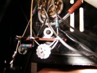
The rather blurred image shows one lead(left of screw)as caddock resistor lead. The gold lead is a hidden 18K resistor going to the cathode of tube #2. The resistor (horizontal ) measures as a 25ohm in circuit. The other lead at the junction of the 18K and the 25ohm resistor is a 233ohm going to pin3 of this tube.
Going for another drink.
Joe
Going for another drink.
Joe
TRANSCEDENT PSYCHES
Hi Joe,
It's a wild guess...this caddock resistor is connected to a split cathode resistor at the input tubes' cathode,sharing a fixed resistor (the coloured one,and then the little pot).
Now that pot would serve to set the input sensitivity of the input stage.(grid bias.)
It's just a guess,I may be off.
Mike Sanders is going to hate me for all that guesswork...
Cheers,
Rectifier upgrade
Hi All,
I found a new post on the loonie bin. There is a newer and better IXYS hexfred or hiper fred.Asylum link for new IXYS diodes
Review of new Hiper Fred
Since I found my stash of diodes in my stash of everything, FIgure I might as well try the HexFred's first in my quickies.
BTW IXYS does make a FWBR, in both Hex and Hiper. dunno the model---
Regards,
Mitch
SUPER FRED
Hi,
I am not sure these interesting new rectifiers will make an audible difference in this particular amplifier though.
The 5AR4 should smoothe over any peaks from the diodes.
What could be audible is the lessened RFI of the diodes in the whole of the audio system.(less mains pollution)
All in all interesting info.
Thanx Mitch.
Joe,
How are the input tubes heated?AC?DC? And if DC how is it done?
Cheers,
- Status
- This old topic is closed. If you want to reopen this topic, contact a moderator using the "Report Post" button.
- Home
- Amplifiers
- Tubes / Valves
- Quicksilver KT88 mono 60watt amp schematic