small film caps paralleling big electros simply can't do all of what is often claimed by audiophiles
lots of the numbers have been worked for you if you can't do them yourself
now adjust for >400uF, working into 10s-100s of kOhms as typically found at an amp's input instead of the 4 Ohms speaker crossover example above...
lots of the numbers have been worked for you if you can't do them yourself
the worst number I see on Bennic's site for "low loss" BiPolar Electros is 20% DF at 10 KHz
|Xc| = 1/(150u*2*pi*10KHz) =~ 100 mOhms
20% DF gives 20 mOhm ESR
1/(2*pi*RC) = 1/(2*pi*20m*0.22u) = 34 MHz
that is the frequency where 0.22uF "cuts DF in half"
even 100x worse DF/esr numbers won't have audio frequency effect
as mentioned the parasitic LC resonance from the parallel connection will occur lower than that
for even 4 Ohm drivers 20 mOhm is 0.5 % for ~= 0.05 dB response difference so the "high"/unbypassed ESR is not itself expected to have any audible audio frequency consequence
now adjust for >400uF, working into 10s-100s of kOhms as typically found at an amp's input instead of the 4 Ohms speaker crossover example above...
small film caps paralleling big electros simply can't do all of what is often claimed by audiophiles
Of course. And I don't consider this to be an "audiophile" circuit either. "Audiophiles" like their caps to be big and conspicuous.

lots of the numbers have been worked for you if you can't do them yourself
Of course. A lot of the problems with caps is not employing circuit design that mitigates their undesireable characteristics. Like
now adjust for >400uF, working into 10s-100s of kOhms as typically found at an amp's input
That's a typical topology and the math "proves" that it works.
Have there been any double blind tests done with coupling caps? I would be interested in the results. I'm going to do some testing myself, but it won't be "blind."
you cn see impedance measurements http://www.diyaudio.com/forums/lounge/200865-sound-quality-vs-measurements-784.html#post3286275
if you count the decades correctly you can tell that the Z doesn't rise above the ESR floor of the big electro until 100 kHz - the added film bypass caps aren't doing anything in the audio region
since the added film Caps barely "pass" more than 1% of audio compared to the Electro ESR in the audio region it hard to understand how they are so selective as to pass distortion preferably enough to make a difference
Last edited:
you cn see impedance measurements http://www.diyaudio.com/forums/lounge/200865-sound-quality-vs-measurements-784.html#post3286275
if you count the decades correctly you can tell that the Z doesn't rise above the ESR floor of the big electro until 100 kHz - the added film bypass caps aren't doing anything in the audio region
since the added film Caps barely "pass" more than 1% of audio compared to the Electro ESR in the audio region it hard to understand how they are so selective as to pass distortion preferably enough to make a difference
All true. But there is more than frequency response to consider. Check out Bateman's research. He demonstrates that different caps have different distortion profiles, and he also claims that schemes like paralleling cap types can reduce some of this distortion.
An electrolytic used improperly has a nonlinear transfer function. Ceramics have a nonlinear transfer function. I was a capacitor skeptic until I recently checked out some research including Bateman's work (which I am still scrutinising) and revisited Walt Jung's comments on choosing capacitors. There's a lot of bull out there regarding capacitors, but treating all caps as ideal within a given bandwith is folly too.
Again, clever circuit design can mitigate most of the nonlinearities of popularly used caps, just like any other device.
since the added film Caps barely "pass" more than 1% of audio compared to the Electro ESR in the audio region it hard to understand how they are so selective as to pass distortion preferably enough to make a difference
Check out all the subjective claims and pontificating about these caps.
Vishay R. Film Caps
" Sound: I was tipped by Klaus Witte of Germany to try this capacitor as a bypass cap for the Mundorf M-CAP SUPREME. I tried them as a bypass for the tweeter series caps in my Progress speaker and I must say I am very impressed! To get straight to the point they don't change a Supreme into a Supreme Silver-Oil but they really do clear things up. I must admit I was skeptical at first as the value is only 10nF (0,01uF) - and the caps in the Progress are 12,6uF. The difference is most noticeable with classical music but also good quality recordings of jazz and fusion benefit: No change in sound stage width or depth but there is more "concert hall acoustics" that let you get into the recording more. Not as liquid as silver/oil but they take away the "grainy" edge from the Supreme's. A gain in clarity and transparency making instruments better separable from each other, the violins in an orchestra are a group of individual violins instead of one mass. Jazz drum brushes sound more like a brush than a "shush".
Verdict: Can’t live without them! – Use them as bypass cap with any capacitor, they cost practically nothing!"
Oh my, sounds like a magic bullet.
By the way, "practically nothing" starts at $1/cap for 0.01 uF.I am dubious about claims like this but I will still do some trials of a couple of different caps and techniques. I will see if I actually hear a difference. But one thing I do know, you can design a circuit that works around a lot of the shortcomings of capacitors.
And Bateman actually reports some paralleling distortion reductions results.............Check out Bateman's research. .............. he also claims that schemes like paralleling cap types can reduce some of this distortion..............
@ -~100dB he states a figure of ~1.5dB reduction in distortion foir the paralleled case.
So I ask the question:Check out all the subjective claims and pontificating about these caps................................I am dubious about claims like this ................
Could fast transients be promoting some ringing in the parallel combination?
Could that ringing be adding to the audio signal?
I try to replace the DC blocking capacitor of my Revel B15a internal amp. and found that it is with 330uf , of course , no film possible , I have good 220uf in hand , is it OK to replace 330uf with 220uf in this occasion ? Will it impair its performance ? I heard this big value is important for low end response .
I have replaced my BAT amp. before and it is only with 3.3uf film capacitor only , why that big difference ? Is BAT not intended as bass amp. It is almost flat to Zero Hz .
Yours kind reply to this is appreciated .
Larry
What happens with the genuine 330uF capacitor?
For this question must be found a clear answer before one gives any advices.
I think the internal amp is this device:
Product Review
Are there a schematic for download?
And Bateman actually reports some paralleling distortion reductions results.
@ -~100dB he states a figure of ~1.5dB reduction in distortion foir the paralleled case.
Yes, I'm still reading his work. 1.5 dB reduction is significant and worthwhile.
So I ask the question:
Could fast transients be promoting some ringing in the parallel combination?
Ringing from the circuit or ringing from the parallel combination? I don't know, but even a good idea executed badly can and will degrade performance.
Could that ringing be adding to the audio signal?
We both know that many people have been fooled into mistaking "ringing" or other distortions for "increased clarity" or "detail not present before" ad nauseum.
My issue, Andrew, it that I can't justify paying $1.00 for a 0.01 uF capacitor or $20.00+ for a coupling capacitor (surf that website I linked to, very expen$ive stuff) without a very good reason. All that slick talk on that website is not what I call a good reason. From some of the claims made, you would think that the people writing them could hear a mosquito fart half way around the world.
Last edited:
Revel states that the low frequency (-3db point) is 18Hz.If your input capacitor is 330µF your input impedance would be about 27Ω)for a -3db point of 18Hz. R=1/(2*PI*F*C), 26.79=1/(2*3.141*18*330E-6). If your input impedance is that low, what are you driving it with?
Even if your input impedance was 1000Ω (which is still low for almost any amp) you would only need an input capacitor of 8.8 µF for a -3db point of 18Hz.
Even if your input impedance was 1000Ω (which is still low for almost any amp) you would only need an input capacitor of 8.8 µF for a -3db point of 18Hz.
Last edited:
Andrew, is there any reason to think that using this capacitor ECQ-V1H103JL Panasonic Electronic Components | P4513-ND | DigiKey in parallel would not yield similar results? If you buy 10 they're 20 cents apiece.
Yes, more to consider than FR: phase. Most people neglect the phase effects of high pass filter formed with blocking capacitors.
Group delay of 6Hz 1st order high pass filter badly smears phase response to well above 200Hz. Effects 20-100Hz in time domain are horrible; as easily seen when passing square wave through filter:
100Hz:

40Hz:

20Hz:

With speakers capable of real square wave performance, the audible difference is easy to distinguish.
National Semiconductor (acquired by Texas Instruments) application note AN-1490 states:
Likewise recording bass accurately is problematic with coupling caps found in recording chain.
Total impact of coupling caps alone makes truly accurate bass reproduction very difficult. This is further complicated by reactive behavior of speaker system.
Increasing filter order only makes matters worse.
Regards,
Andrew
Group delay of 6Hz 1st order high pass filter badly smears phase response to well above 200Hz. Effects 20-100Hz in time domain are horrible; as easily seen when passing square wave through filter:
100Hz:
40Hz:
20Hz:
With speakers capable of real square wave performance, the audible difference is easy to distinguish.
National Semiconductor (acquired by Texas Instruments) application note AN-1490 states:
In listening tests at National's sound room evaluating different circuit components used in the LM4702 demo amplifier, there was one part whose negative effect on audible signal quality was undeniable. A DC blocking capacitor on the input of the LM4702 degraded sound quality. In multiple listening tests, with different participants and at various locations around the country, the negative effects of even the best film and foil polystyrene DC blocking input capacitors in the audio signal path was confirmed.
Likewise recording bass accurately is problematic with coupling caps found in recording chain.
Total impact of coupling caps alone makes truly accurate bass reproduction very difficult. This is further complicated by reactive behavior of speaker system.
Increasing filter order only makes matters worse.
Regards,
Andrew
Last edited:
And Bateman actually reports some paralleling distortion reductions results.
@ -~100dB he states a figure of ~1.5dB reduction in distortion foir the paralleled case.
unsurprising "by the numbers" when you read closely enough to see that he is paralleling a 100 uF electro with 10 uF made itself of 3x parallel 3.3 polypropylene caps
so the value of his parallel bypass C is 10% of the main electrolytic - I don't think most audiophile formulations of "bypass with a small quality film cap" are talking about 10% - the film is then physically similar size as the electro
plus there is the question of the significance of 1-2 dB 2nd harmonic at -100 dB
Fast Eddie D said:Yes, I'm still reading his work. 1.5 dB reduction is significant and worthwhile.
those excusing tube amps regularly point out that few % 2nd harmonic isn't audible (with sine waves, most music - although IMD difference frequency products from nonlinearities generating 1% 2nd harmonic stand out like a sore thumb with multiones)
but there is no DBT evidence I know of that -100 dB low order distortions are audible - try finding recordings of live performers in music with 100 S/N anywhere in the recording where the mic feeds are live -= certainly no recording ever going through any analog storage in the recording, playback - pro audio tape, vinyl don't have that sort of noise floor
Last edited:
unsurprising "by the numbers" when you read closely enough to see that he is paralleling a 100 uF electro with 10 uF made itself of 3x parallel 3.3 polypropylene caps
so the value of his parallel bypass C is 10% of the main electrolytic - I don't think most audiophile formulations of "bypass with a small quality film cap" are talking about 10% - the film is then physically similar size as the electrolytic
That's true but is it equivalent to using a 110 uF cap? That value is well within the tolerance of most electrolytics.
Your comment ignores the alleged reason why this works.
plus there is the question of the significance of 1-2 dB 2nd harmonic at -100 dB
True but that's what audiophiles get into.
It also depends on the distortion profile. Are you aware of psychoacoustical considerations? Human hearing is acutely sensitive to very faint echos. And we all know that some harmonic distortion isn't noticeable or objectionable in small quantities, while IM distortion is.
those excusing tube amps regularly point out that few % 2nd harmonic isn't audible (with sine waves, most music - although IMD difference frequency products from nonlinearities generating 1% 2nd harmonic stand out like a sore thumb with multiones)
Of course. It also occured to me that this might be the reason some people like these huge capacitors- you might as well put an antenna right in the circuit. I find it hard to believe that putting a physically enormous capacitor in a high impedance circuit wouldn't have a negative effect.
but there is no DBT evidence I know of that -100 dB low order distortions are audible - try finding recordings of live performers in music with 100 S/N anywhere in the recording where the mic feeds are live -= certainly no recording ever going through any analog storage in the recording, playback - pro audio tape, vinyl don't have that sort of noise floor
You're correct for the most part. But "live" music sounds live because of the background noise and reverberations. Our hearing is very sensitive to these reverberations. Masking them may create an audible difference even if we're not immediately aware of it.
Yes, more to consider than FR: phase. Most people neglect the phase effects of high pass filter formed with blocking capacitors.
Group delay of 6Hz 1st order high pass filter badly smears phase response to well above 200Hz. Effects 20-100Hz in time domain are horrible; as easily seen when passing square wave through filter:
100Hz:
View attachment 317983
40Hz:
View attachment 317984
20Hz:
View attachment 317985
With speakers capable of real square wave performance, the audible difference is easy to distinguish.
National Semiconductor (acquired by Texas Instruments) application note AN-1490 states:
Likewise recording bass accurately is problematic with coupling caps found in recording chain.
Total impact of coupling caps alone makes truly accurate bass reproduction very difficult. This is further complicated by reactive behavior of speaker system.
Increasing filter order only makes matters worse.
Regards,
Andrew
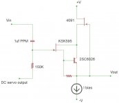
I agree. This type of phase inacuracy between the different bands of the audio spectrum can destroy the soundstage and perception of the music; DA distortion as well. I like to use 1uf PPMF, but this requires a high input inpedance >100K. Then use a simple buffer to drive the input stage. PPMF caps much larger than 1uf are impractical and expensive.
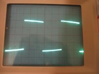
This buffer uses a tiny low conductance J-fet, intended for piezo mic applications. This J-fet acts as a summing point between the DC servo output or "virtual GND" reference and the input signal. The waveform is 20Hz square wave near full power.
Attachments
Last edited:
Yes, more to consider than FR: phase. Most people neglect the phase effects of high pass filter formed with blocking capacitors.
Group delay of 6Hz 1st order high pass filter badly smears phase response to well above 200Hz. Effects 20-100Hz in time domain are horrible; as easily seen when passing square wave through filter:
100Hz:
View attachment 317983
40Hz:
View attachment 317984
20Hz:
View attachment 317985
With speakers capable of real square wave performance, the audible difference is easy to distinguish.
National Semiconductor (acquired by Texas Instruments) application note AN-1490 states:
Likewise recording bass accurately is problematic with coupling caps found in recording chain.
Total impact of coupling caps alone makes truly accurate bass reproduction very difficult. This is further complicated by reactive behavior of speaker system.
Increasing filter order only makes matters worse.
Regards,
Andrew
That quote from National is a real eye-opener.
But I don't understand what you are trying to show with the plots of square waves at different repetition rates. I see zero phase effects. We wouldn't be able to see phase shifts, from those plots, anyway, since there is no reference to the original phase. A phase shift would mean that the vertical portions of the waveforms would move left or right, compared to the original.
If you are looking at the exponential decay of the tops of the square waves, that has nothing to do with phase. It is the RC filter time constant causing the temporarily-constant-DC voltage to decay, as capacitors always do, through a resistance. The lower repetition rates have longer periods, thus longer to decay, makiing the effect look more pronounced. You didn't mention what capacitance or resistance values were involved, either.
The solution for that exponential voltage-decay effect is trivial: Use a larger capacitance value, or a larger resistance. You can make them stay as flat as you want, for as long as you want. It might also be possible that the voltage-decay effect could be exacerbated by a source that can't supply enough current, or something in the circuit configuration that prevents it from doing so.
Last edited:
I agree. This type of phase inacuracy between the different bands of the audio spectrum can destroy the soundstage and perception of the music; DA distortion as well. I like to use 1uf PPMF, but this requires a high input inpedance >100K. Then use a simple buffer to drive the input stage. PPMF caps much larger than 1uf are impractical and expensive.
This buffer uses a tiny low conductance J-fet, intended for piezo mic applications. This J-fet acts as a summing point between the DC servo output or "virtual GND" reference and the input signal. The waveform is 20Hz square wave near full power.
I agree that frequency-dependent phase inaccuracy could be bad for soundstage imaging. But I see no "smearing" of the vertical portions of the waveforms, in Andrew's post.
Also, I cannot see how using an input capacitor, even a "PPMF", would solve a problem caused by using an input capacitor. And if you are using a DC servo, then why have a blocking capacitor??
Also, it appears that your square wave is significantly distorted, maybe due to a blocking-capacitance value that is too low, or a resistance value that is too low, or a source that cannot supply enough current, for some reason. Or, maybe the DC servo's time-constant is acting too quickly, and trying to correct the temporarily-constant-DC parts of the square wave back to zero.
(Assuming your scope probe was properly compensated, the concave shape of the decay of the square wave voltage is not what would typically be caused by an RC discharge effect. So maybe it is just the servo...)
Last edited:
But I don't understand what you are trying to show with the plots of square waves at different repetition rates. I see zero phase effects. We wouldn't be able to see phase shifts, from those plots, anyway, since there is no reference to the original phase. A phase shift would mean that the vertical portions of the waveforms would move left or right, compared to the original.
The solution for that exponential voltage-decay effect is trivial: Use a larger capacitance value, or a larger resistance. You can make them stay as flat as you want, for as long as you want.
The filter applied in pictures is 1st order Butterworth filter with 6Hz corner.
Square wave is the reference. Everything seen changing shape of wave is phase effect. All harmonics remain at same amplitudes.
Increasing RC as solution seems trivial, but typical input/output impedance of audio electronics narrows choices.
Fat caps lose out to fat bonus for trimming costs, at least with commercial interests.
1-2dB droop in peak of every bass transient sticks out a lot more than dropping -100dB 2nd harmonic 1-2dB.
Regards,
Andrew
A square wave, when put through a filter with significant frequency-dependent phase shift, which would vary the phase angles (start times) of the square wave's set of odd-order Fourier components (which arithmetically sum to form the shape of the square wave), would mostly show up as overshoot and ringing, of the output square wave, and also as slight distortions of the rising and falling portions of the leading and trailing edges.
The filter applied in pictures is 1st order Butterworth filter with 6Hz corner.
Square wave is the reference. Everything seen changing shape of wave is phase effect. All harmonics remain at same amplitudes.
Increasing RC as solution seems trivial, but typical input/output impedance of audio electronics narrows choices.
Fat caps lose out to fat bonus for trimming costs, at least with commercial interests.
1-2dB droop in peak of every bass transient sticks out a lot more than dropping -100dB 2nd harmonic 1-2dB.
Regards,
Andrew
HOGWASH.
Try a 0.2 Hz, or 0.02 Hz, corner frequency. Or try a 600 Hz repetition rate.
A 6 Hz corner frequency would never be used, if you wanted acceptable bass response.
Hmmm.... Now that I think about it, you might actually be correct about that being a phase effect (more likely a phase effect AND a way too high corner frequency). But you didn't mention anything about a Butterworth filter in your original post. You implied that the effects were due to a DC blocking capacitor.
At the very least, you should show the input and output square waves plotted on the same scale, and give full circuit details.
Also, please SPARE us from your ill-conceived anti-commercialism. These days, that's a political viewpoint, and not allowed here.
Last edited:
- Status
- This old topic is closed. If you want to reopen this topic, contact a moderator using the "Report Post" button.
- Home
- Amplifiers
- Solid State
- Question on input dc blocking capacitors