I guess the difference in results for triode versus pentode is that they are taking into account the triode's plate feedback (and load). So the SE triode is getting degenerated toward linear law, and the LTP pentodes can get degenerated toward square law (if they start above that). Something like that. I guess we should straighten the maths out here to see exactly what's going on.
Eventually, a real circuit needs measurement, with an FFT analyzer watching while the R gets tweaked.
This is all a good argument for making a dynamic gm or gain analyzer. A moderately slow sawtooth sweep input with some small 1 KHz added on, with an X-Y scope readout of the test circuit's (or "DUT") 1 KHz amplitude output versus the DC "signal" sweep. A flat line would be linear gain. This could have some vert. AC gain put into it to show small variations. Similar to the "wing-spread" plots that Self and Cordell use.
Last edited:
Just for comparison, here is an older TV sweep tube, 6CB5, that has much less aggressive power law curves, probably near 3/2 power.
And the aggressive 6HJ5 again for comparison. A Mosfet in a bottle.
The 6CB5/A has been used quite successfully for a SET configuration, not really surprising given its "old" style tube curves.
http://frank.pocnet.net/sheets/137/6/6CB5.pdf
http://frank.pocnet.net/sheets/084/6/6HJ5.pdf
And the aggressive 6HJ5 again for comparison. A Mosfet in a bottle.
The 6CB5/A has been used quite successfully for a SET configuration, not really surprising given its "old" style tube curves.
http://frank.pocnet.net/sheets/137/6/6CB5.pdf
http://frank.pocnet.net/sheets/084/6/6HJ5.pdf
On that WE "harmonic equalizer",
I think I have seen another version where a current sense resistor was put in the B+ lead from the OT center tap. Variation in current up there (in class A) contains the odd harmonics. Then the signal from that was RC coupled down to the two tube grids to cause cancellation. (effectively the same as the R in the tail approach, but no tail required here, and more gain/effect possible) Notice that this tends to keep the common mode current draw constant.
There was some issue about biasing, the C coupling and transients that way I think. A non-linear R Isense up top might allow it to work better with varying load Z, so a damper diode might be substituted for the R up top. Some R divider V Fdbk scaling might be called for, for the signals to the grids. This makes it more flexible than trying to put the damper in the tail, since its conductance does not have to be matched to 1/gm due to the R divider scaling available.
Anyway, that B+ Isense resistor/damper can be used to do other interesting things. If one returned that distortion sense to just one side of the tube pair's grids, it would tend to keep total B+ current constant, without affecting the driven tube side. This is a similar in effect to the "anti-triode" setup, where one tube mirrors the other driven tube to get constant total current. With a grounded cathode on the driven side, it is definitely operating in a SE mode environment. So another way to get near SE using P-P. (kinda takes the odd harmonics and turns them back into even harmonics)
Last edited:
Sorry about that. The paper got OCR scanned by Broskie and ended up with lots of errors in the math. I think the original paper has the math right, can probably find an original with Google.
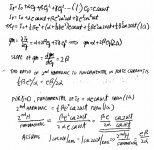
For you interest, I double check and rewrite the formula how he derived the Ratio of 2nd harmonic to fundamental of the plate current Ip. This is in case you are interested.
Attachments
So the objective of the limited degeneration is to remove the 3rd harmonic (curvature in the gm curve). But a sloping gm curve means lots of 2nd harmonic already. P-P gets rid of the 2nd harmonic then. (and class A prevents turning that stuff into 3rd harmonic) So anything with an upward curving gm curve can benefit from a little degeneration. Unfortunately a lot of gm curves bend upward at low current and downward at high current. We really need the plots of gm for power output tubes to determine how to optimally operate them (bias, degeneration R).
Interestingly, the later high gm tubes (usually dreaded) are the more likely to be fixable then, since they are more likely to be curved upwards consistently (gm versus Vg1 ).
And since the R degen. tends to be around 1/gm, but the gm curves typically need less correction at high current, a non-linear R with more aggressive non-linearity than 3/2 power law would seem better at reducing the dynamic R at higher current. So instead of a damper diode (3/2 power), what one wants is a "dioded" Mosfet (square law, R divider from drain to source for the gate V) Seems counter-intuitive though that a higher non-linearity R would help. Some experimenting called for I think.
Last edited:
Those of us familiar with Eddie's participation in the DIY forum-verse as far back as the mid 90's - Decware, etc, where he earned the nick name "Obi-Vaughn" for his sagacity, as well as his short lived commercial tube amp business a few years back ("Carina" EL84 SE) , would certainly welcome his renewed participation in the conversation - if he's still around.
About 5yrs or so ago, I commissioned him to build me an EL34 SE amp using OPT by Bud Purvine - it took at least a year to receive, and was damaged in transit and required complete rebuild. Sounded very nice, and was very tidy work.
I had an opportunity to hear Allen's DPA300s at VSAC (2003?) - in my limited experience, it was the most musical, transparent, vacuum tube amp I've encountered - followed closely by a DIY project by forum member nerdorama
Any link to this DIY Nerdorama project?
try a PM?
all I can remember is a lot of options, iron and was 6BG4(?) P/P - sorry I can't remember more than that - a lotta stuff crammed into that one weekend
6BG6 maybe? Probably class A.
---------------------------------------------
I just realized a flaw in my reasoning above about using a higher non-linearity degeneration R tail. For class A, the tail current is not varying along with an individual tube's current, it is only rising with the net change of gm for both tubes, which is much less, since one goes up and the other down. So no need for the degeneration R for the tail to be so aggressively non-linear. The common mode current draw is a measure of total gm, and that is what is being corrected.
This gives a nice simple time domain picture of the WE harmonic neutralizer for either scheme, R in the tail, or R in the B+ with feedbacks to the grids. It just lowers the common mode current when total gm gets too high, which then drops the total gm back down.
And so an I (common mode) sensing device, which does the I to V conversion with the same law as the active gain devices do the V to I, should provide a linear gm control loop. Hmmm, and since we are trying to control nominally 3/2 to 2 power devices, I'm right back to a damper diode or "dioded" Mosfet for the sensing device.
Deja-Vu, I must be going in circles this morning. Well, at least the WE harmonic neutralizer is much clearer.
Last edited:
And so a CCS tail doesn't work properly in class A because it doesn't have the correct common mode I to V sensor to control the total gm.
You need a damper diode or "dioded" Mosfet in the B+/CT lead for correct common mode I to V sensing, and that controls the current of a slightly varying "CCS" tail.
Solved!!!! Who-Hoo!! Have a great day!
Hmmm, except that just gets one back to constant current if it has much loop gain.
More work needed.............. Maybe just unity CM loop gain.
Yes, and the active gain devices must have consistant gm power laws, no S curves allowed.
That explains why the WE H-N doesn't work very universally. And makes a gm analyzer for tubes/P-P stages a high priority.
exception:
if the gain devices have sufficiently symmetrical S curve gm, then one tube variation compensates for the other, and one can use the average curve, which will then probably just be square law (straight gm ramp) with no need for correction in class A P-P.
Last edited:
I am still trying to read the paper, I don't know how he came up with (\alpha^2/4g). I followed all the derivations and all of a sudden this term pops up and he use that to judge the linearity. Can you explain how that come from?I'm still confused as to why Kiebert's paper says triodes and pentodes have a different 3rd order coefficient polarity. From looking at gm curves, it seems that either can have upward curvature, at least over part of their gm curve.
The point anyway was that just putting a CCS in the tail is not a magic cure all. Some finite impedance is more likely to give linearity. From looking at various gm curves like the Mosfet, when graphed versus gate V drive (Self, 4th ed. pg 502), the gm curve is a nice linear ramp. The derivative of square law V to I gives a linear ramp for gm. A power law above 2 gives an upward curving gm curve (on Vg base scale), and a 3/2 power law gives a downward trending curve. Since tubes are nominally 3/2 power law, but typically more like square law or above at low current due to grid/cathode wire proximity effects, their curves can vary in curvature. They get more toward a linear power law at high current, like Mosfets do. Cathode current saturation effects also round off the gm curve at the top.
The old low gm tubes can be closer to 3/2 power law. The later high gm tubes tend to start out above square law at low current and drop toward 3/2 power law or lower at high current. So the resistive tail can be useful in the lower current range. Unfortunately, most output tubes don't have gm graphs on their datasheet. But one can probably figure that most later TV sweep tubes are square law or above. One could try to measure that and calc off the plate curves. Some tubes are obvious though with clearly accelerating current gains as -Vg1 goes to zero.
As Broskie mentions above, the optimum tail R tends to be around 1/gm of the tube. I think a crude way of viewing this is that one is degenerating with a linear resistor, so one is effectively reducing the power law for the combo. If one gets it down to square law with linear gm ramps, it is ideal for class A combining. Since gm increases with current, it could be useful possibly to have a non-linear R that (dynamically, ie, AC R) drops with current. I have seen designs where the tube was degenerated with a TV damper (power diode) tube. Primarily they were using it to just get a bias voltage drop, but it has the additional effect of dropping the tube toward 3/2 power law. Unfortunately, all this degenerating stuff lowers the gm, and increases the Rp, so its only something for "touch-up" fixes.
Do you have any link? I really don't know enough about tubes in all the stuffs you said in this post. Why is triode 3/2 power law etc.
It seems to me for best linearity, you want gm to be constant(horizontal in gm vs grid voltage) and high. When there is a slope on the gm curve, you already have distortion.
From looking at the gm curve in Fig 2. Seems like if the slope is a linear ( straight line) you have only 2nd harmonics. The curve part means there is high order distortion. The reason is because the derivative of gm lower all the power by 1, the \beta term become linear and therefore is straight line. But the 3rd harmonics because a square term, so you have a line that is curved. Am I correct?
Thanks. I still have a lot to learn about tubes.
Last edited:
Hey Smoking-Amp.
It just dawned on me, how useful is this gm curve and adjusting the cathode resistor thing?Please tell me what you think:
This whole gm vs grid voltage thing is based on keeping the plate voltage constant. We all know the current change when you change the plate voltage. This graph or fixing the graph become useless when the plate voltage start changing on the triode!!!
This might be useful for penthode or tetrode because of the high output impedance that the plate current don't change much with changing plate voltage. So the gm vs grid voltage mean something. But not for triode.
I am still trying to read the paper, I don't know how he came up with (\alpha^2/4g). I followed all the derivations and all of a sudden this term pops up and he use that to judge the linearity. Can you explain how that come from?
It looks as if he is saying that he will use the ratio of gain divided by distortion as a "figure of merit." He is defining the distortion to be the ratio of the coefficient of the cos(2wt) term divided by the coefficient of the cos(wt) term, which is g/(4 alpha). The gain is taken to be alpha, and so his "figure of merit" comes out to be alpha/(g/(4 alpha)), i.e. 4 alpha^2/g.
Looks like he made a mistake with getting the 4 in the denominator instead of the numerator. (Maybe another of the OCR errors? But a bit hard to imagine how that happened!) In any case, since he then observes that he can equally well rescale his figure of merit definition by a universal factor, it doesn't matter in the end if he got the 4 in the wrong place, and he can just use alpha^2/g as the figure of merit.
Chris
I gave up pointing out the error, yes the 4 is at the wrong place.It looks as if he is saying that he will use the ratio of gain divided by distortion as a "figure of merit." He is defining the distortion to be the ratio of the coefficient of the cos(2wt) term divided by the coefficient of the cos(wt) term, which is g/(4 alpha). The gain is taken to be alpha, and so his "figure of merit" comes out to be alpha/(g/(4 alpha)), i.e. 4 alpha^2/g.
Looks like he made a mistake with getting the 4 in the denominator instead of the numerator. (Maybe another of the OCR errors? But a bit hard to imagine how that happened!) In any case, since he then observes that he can equally well rescale his figure of merit definition by a universal factor, it doesn't matter in the end if he got the 4 in the wrong place, and he can just use alpha^2/g as the figure of merit.
Ha ha, I gave up pointing out everything already. Yes the 4 is at the wrong place for sure.
I understand he meant gain/distortion to get that. But my real question is why. How can he justify this. He went through the detail to derive up to one point and just through out using the figure of merit with no explanation.
But the more pressing thing is how valid is doing this exercise for triode as this graph is for constant plate voltage only. In real life plate voltage change with input in common cathode stages. That seems to make this exercise a moot point.
Chris
I understand he want gain/distortion. But he did not explain why he do that. The distortion part already have the gain in it. He took the pain to derive all the formulas but just throw that out without any justification.
But more important thing is in my last post. The graph is for constant plate voltage. The plate current of triode vary with plate voltage. So when the plate start to swing, all the exercise in this is for not!!!
You guys are not alone in having problems with the Cooper article, Keith Snook has written a good summary of the issues and provided two additional articles by Roddam worth reading.
Alan - there seems to be a small typo in equation 1a of post #66, shouldn't the last term be 1/4γe3cos3ωt? Not that it matters much, since γ=0 in Cooper's article.
Alan - there seems to be a small typo in equation 1a of post #66, shouldn't the last term be 1/4γe3cos3ωt? Not that it matters much, since γ=0 in Cooper's article.
Any link to this DIY Nerdorama project?
May be something similiar to this one? (via Google)
An externally hosted image should be here but it was not working when we last tested it.
The Child -Langmuir model for the triode: Ip = G(Vg1 +Vp/mu)^1.5
Supposed to be a good approximation.
But for real triodes and pentodes (Vscreen takes place of Vplate) the power law effect at the grid is closer to 2.0 power (square law) or higher due to grid wire proximity (to cathode) effects for lower currents. (still 1.5 power law at plate or screen grid) Then gradually reduces in power toward 3/2 (=1.5) then linear at higher current, then bows over (less that 1 power) at high current due to cathode saturation (and plate voltage vanishing) effects. (this power law mis-tracking between plate and grid1 is (at least part of) the cause of varying Mu in real triodes)
Looking at the 6DR7 datasheet below, page 5 small signal triode, and page 7 power triode, for the gm curves versus Vg1, you can see the upward curving nature at lower currents. Then approach to linear gm ramp at higher current (which would be square law), then finally bowing over on the page 5 section 1 graph at high end current. The curves tend to be the same shape for different plate voltages.
So these tail R fixes would only apply to upward curving graphs, but the power tubes tend to have them. (pentodes too) But since their power law changes (decreases) toward higher current, the tail R would seem to need to vary with I. From the analogy above (earlier) of controlling common mode gm, it would seem useful to use a non-linear current sensing R with I to V corresponding to the V to I in the active devices for resulting linear control of gm. Constant gm sum across the class A signal range being the goal.
So forget the hopeless math derivations. I was just saying that one might want to try some various options for class A tail degeneration to see if it would linearize a power output stage.
http://tdsl.duncanamps.com/sheets/6dr7/6dr7.pdf
One caution, a lot of datasheets present gm curves versus current. The square law gm then bows over oppositely (or downward instead of upward) instead of a linear ramp. The gm versus current graphs are useful for current source tail setups, since current is confined to a constant sum. So one can sum two tube gm graphs (one flipped) to get total gm in class A. Obviously this will end up a big bump in the middle (unless corrected).
E55L shows the gm plotted both ways, versus Vg1 on page 7 and versus Ip on page 9:
http://frank.pocnet.net/sheets/009/e/E55L.pdf
for triode or pentode 3/2 power model: gm = k(Vg1)^0.5
[well, triode model: gm = k(Vg1+Vp/mu)^0.5 and pentode model gm = k(Vg1+Vscr/mu)^0.5 ]
for Mosfet square law (2.0) power model: gm = kVg
for bipolar exponential law model: gm = kI
Last edited:
Bipolar transistors like a CCS tail for constant gm sum. Triodes and Mosfets do not.
They end up with a big gm hump in the middle with a CCS. This is why CCS'd differential tube pairs produce 3rd and higher odd harmonics.
So the R or non-linear R tail is an approach to linearize them when differentially organized. One can also put the "R" in the B+ (OT center tap to B+) lead and send NFBKs to the grids. (that's one version of the WE harmonic equalizer)
So what one needs is a gain analyzer for tube circuits, similar to the "wing-spread" plots used by Self and Cordell. One could just use a sawtooth or triangle waveform to sweep across the input signal range (and an inverted signal for diffl. setup) with a small amount of say 1 KHz sine wave added to it. Then at the output of the stage under test, one would monitor the amplitude level of the 1 KHz component (filtered and demod'd) on an X-Y scope vertical channel, and the sawtooth or triangle sweep signal on the horizontal. (some linear AC gain applied to the vertical channel to see small gain variations) A flat line readout would be the linear gain case.
With this analyzer, one could distortion debug tube stages in an amplifier. Finding the optimizer "R" (or non-linear R) tail for a differential type stage would be easy.
Some power beam tube gm plots (last page):
http://frank.pocnet.net/sheets/123/1/10JA5.pdf
http://frank.pocnet.net/sheets/123/6/6LU8.pdf
This R tail linearization may only require a small non-linearity in the R tail for class A differential type outputs since the gm of the two tubes adds to a near constant as 1st order (class A sum). And triodes already do internal linearization from plate feedback, so the tail correction would be even smaller for them.
But it --MAY-- even work for a class AB type output stage. Since one is then mainly looking at the gm variation of a single tube. A damper diode tube tail (3/2 power V/I) or "dioded" Mosfet (square law) tail may work in that case, as the non-linear R. Obviously getting tracking with the much wider gm variation will be harder. That's where the gain analyzer comes in.
The "diode'd" Mosfet uses an R divider (drain to source, tap feeding the gate), so is adjustable. Although I think two adjustments are needed, one for nominal resistance, and another for non-linear curvature. So both divider resistors would be pots, top one adjusts output V to I scale, bottom one adjusts relative gain on the gate. (is this working, or giving the same thing? maybe a variable degen. R under the Mosfet instead, for the 2nd adjustment)
So you just set up a tube amplifier with one of these adjustable tails under the output stage, connect the gain analyzer, and tweak away until the gain is flattest.
Last edited:
- Status
- Not open for further replies.
- Home
- Amplifiers
- Tubes / Valves
- Question and comments on SE vs PP by Eddie Vaughn