HiHello,.. I previous postings from APEX was schematic with FETS to short circuit input stage for turn on delay. I cant find in threads
Did some it and can posting ?
Please give your precise topic (page) where the round protection for this amplifier?
thanks
Last edited:
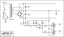
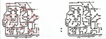
schematic here below ......first pic for NMOS second pic for radio
Alex.
Thank you for Turn On off schematic...
do you have circuit description too ?
Thank you for Turn On off schematic...
do you have circuit description too ?
Does somenbody know popular substitute for FET 2N5638 in APEX turn on /off Mute ?
Is by german semiconductor distributors not available
Alex mm thanks for the sematic!, ... Is this amplifier has a chance to be reworked with a pair of complementary output 2SC5200/2SC1943?schematic here below ......
Alex.
Regards and cheers !!
Hi Mile!
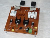
I made this Quasi amplifier (picture below), but two things bother me: Why security diodes 1N4007 are connecting to the PCB in front of the fuses and why 0,33R/5W resistor is connected to the collector output transistor (2N3773), not the broadcaster?
Mile you do not need to make a correction?
Waiting quick response after I made amplifier!
thanks and cheers
P.S.
Posto slabo mi ide engleski evo prevoda na Srbski:
Izradio sam ovaj Quasi Amplifier (slika dole), no muce me dve stvari: Zasto sigurnosne diode 1N4007 su povezane na PCB ispred osigurace i zasto otpornik 0,33R/5W je povezan na kolektor izlaznog tranzistora (2N3773 povezan na negativnoj grani), a ne na emiter??
Mile molimte odgovori na pitanja da ne treba da napravim korekciju?
Cekam brzi odgovor posto sam izradio pojacavac!!
Hvala i sve najlepse!
Attachments
Last edited:
This amp has awfull THD ratios, not only because it s
working in Class B, but also because of an huge overcompensation.
No way it can be branded hifi, not even as a bass box amplifier....
In a way, it can only disappoint even the most enthusiast beginner..
A sad gift to give them such a misdesign...
Hi Wahab!
Please give a PDF?
Since this can not open?
thanks
Preamplifier fior subwoofer
Hello all!
This amplifier (Quasi amplifier for beginners) I want to use for the subwoofer, so please help with some schematic and PCB for preamplifier for subwoofer.
Frequencies that can be regulated from 20...120Hz with a slope of 12 ...18dB.
This amp I want to include it on output to my stereo amplifier.
Thanks
what is the wattage of small resistors? 1/4 watt or 1/2 watt
Small resistors are 1/4W
Hello all!
This amplifier (Quasi amplifier for beginners) I want to use for the subwoofer, so please help with some schematic and PCB for preamplifier for subwoofer.
Frequencies that can be regulated from 20...120Hz with a slope of 12 ...18dB.
This amp I want to include it on output to my stereo amplifier.
Thanks
Preamp for subwwofer you can find here http://www.diyaudio.com/forums/analog-line-level/167363-mic-line-eq-preamps-11.html
Hi radio ,
I have search for you an better schematic , also tested one . I have done small changes for 2SC 5200 as finals ..... I hope you like it .
Regards Alex.
Attached Thumbnails
Attached Files
Nbip300schematic.pdf.pdf (42.1 KB, 119 views)
QUASI 300 BJT N PCB TOP ALL.pdf (151.8 KB, 107 views)
QUASI 300 BJT N PCB TOP VIEW.pdf (46.5 KB, 87 views)
Dear Alex
Can you post me sprint file for Nbip300 pcb layout at my email rkkatiyar@gmail.com
Thanks
Katiyar
I like this amplifier circuit,
I have been messing around with it in circuitmaker all day.
So far I have done sims with the 2N3055's and the 2N3772's and TIP31a's and TIP32'a.
Mostly stuff I have laying around and I am sure I have enough to build one or two.
With A few tweaks in some of the resistor values I have it doing 80V p-p into a 2 ohm load and 66V p-p onto a 1 ohm load on -/+ 50V rails and 91v p-p into 8 ohms.
This exactly all I need to run my ESL experiments without having to risk my professional amplifiers should any thing go wrong.
And if I need more, it can be easily modified for more if needed.
When I get one built and running I will certainly run it through some heavy tests and post the results here.
My main criteria is to have a 40v to 60v peak swing all of the way down to 1 ohm at 20Khz but 2 ohms is sufficient for now.
The 1 ohm requirement is only for the impedance that the ESL's reflect on the high frequency peaks at 20Khz and at 10Khz this would be 2 ohms.
In the sims this circuit shows a flat response up to 100Khz.
This is a very affordable amp to build out right if one wanted to do so,But like I had mentioned I already have most everything in my parts bin.
This seems to be a step above some of the more very common Quasi Configurations that I have been messing with, and, I am curious to find out what its performance will be like using some common off of the shelf components (transistors) that I have just laying around.
Thanks !!!
jer
Last edited:
little help needed
Hi geraldfryjr
greetings can i use mje 340 mje 350 as drivers want to make your
amp do you have pcb for sharing this my first amp project
warm regards
sameer x1
Hi geraldfryjr
greetings can i use mje 340 mje 350 as drivers want to make your
amp do you have pcb for sharing this my first amp project
warm regards
sameer x1
Attachments

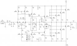
Here is the schematic with my modifications.
The output offset voltage is set to less than 1millivolt (.001v) and the bias is set at about 250 milliamps per output device with the values shown.
Cheers !!
jer
there is no predriver current limit
- Home
- Amplifiers
- Solid State
- QUASI Amplifier for Beginners