Hi Tibi!
I was just planning to start a new thread about creating a Super-405 when I found this one! This looks like an excellent amp! I'm modifying some 405s but feel I won't be able to get the current capabillity that I need in the end.
Interestingly my 405 sounds subjectively better than my 405-2 at the moment. I still have to track down why. 405-2 got new fat power caps, 405 has the original ones. They also have different input op-amps. Did you find that you could alter the sound a lot by changing power caps etc?
I would be interested in building this one when the time is right!
Regards
Patrik
Patrik!
You can also take a look at this thread:
http://www.diyaudio.com/forums/showthread.php?s=&threadid=109771&perpage=25&pagenumber=1
I will try to wake Zsolt up. He was willing to make some changes in his Altium-files in order to make his boards more universal. I suggested some alternative PCMs (printed circuit modules), so that various components could be fitted. We have a contact in China that can make the PCBs, price is fair.
Roger
Patrik Floding said:.... Did you find that you could alter the sound a lot by changing power caps etc?
...
Hi Patrik !
The caps can change the sound a lot, whatever you place them.
")
Power caps will alter the sound over the time and also need a burn-in time which is in directly relation with their construction type and dielectric.
Regards,
Tibi
RogerGustavsson said:Patrik!
You can also take a look at this thread:
http://www.diyaudio.com/forums/showthread.php?s=&threadid=109771&perpage=25&pagenumber=1
I will try to wake Zsolt up. He was willing to make some changes in his Altium-files in order to make his boards more universal. I suggested some alternative PCMs (printed circuit modules), so that various components could be fitted. We have a contact in China that can make the PCBs, price is fair.
Roger
Hi Roger!
I would certainly like to try one (ok, two) of those, as it would slot right into the existing chassis. I assume the Zsolt/Roger 405 has better current capabillity than the original 405-2?
I'm reading up on that thread now.
If you haven't ordered anything yet, I would be interested in 4 boards. (Suitable L-profile alu brackets too..)
Hälsningar
tvicol said:
Hi Patrik !
The caps can change the sound a lot, whatever you place them.
Power caps will alter the sound over the time and also need a burn-in time which is in directly relation with their construction type and dielectric.
Regards,
Tibi
Hi Tibi!
Yes, I noticed changes as the new caps "matured". Also, when I got the amps one of them took almost a week before the caps had reformed to a point where bass was reasonable. The other sounded fine straight away.
A huge change in sound quality came about from parallelling the new big (22mF) supply caps with smaller electrolytics (1000uF in this case). I suspect the big caps cause a slew rate type of limiting of current for fast events.
Patrik Floding said:
Hi Roger!
I would certainly like to try one (ok, two) of those, as it would slot right into the existing chassis. I assume the Zsolt/Roger 405 has better current capabillity than the original 405-2?
I'm reading up on that thread now.
If you haven't ordered anything yet, I would be interested in 4 boards. (Suitable L-profile alu brackets too..)
Hälsningar
Hej Patrik!
Are you also swedish? These PCBs that I hope to get, will be drop-in replacements for the original circuit boards. Yes, the current capabillity will be improved as the power transistors MJ15003 will allow that. There will be no current limiters as in the original Quad 405 or 405-2. I am following the schematics of Bernd Ludwig and Keith Snook. More or less page 10 in this document:
http://www.dc-daylight.ltd.uk/Valve-Audio-Interest/Schematics/QUAD-405-Evolution-May-2008.pdf
Roger
Yes, svensk too! Bor i England, dock.
What you tell me about the boards sound really interesting indeed!
What you tell me about the boards sound really interesting indeed!
RogerGustavsson said:
Hej Patrik!
Are you also swedish? These PCBs that I hope to get, will be drop-in replacements for the original circuit boards. Yes, the current capabillity will be improved as the power transistors MJ15003 will allow that. There will be no current limiters as in the original Quad 405 or 405-2. I am following the schematics of Bernd Ludwig and Keith Snook. More or less page 10 in this document:
http://www.dc-daylight.ltd.uk/Valve-Audio-Interest/Schematics/QUAD-405-Evolution-May-2008.pdf
Roger
RogerGustavsson said:
Yes, the current capabillity will be improved as the power transistors MJ15003 will allow that.
I had a look at the MJ15003, and it sure is a beefy transistor!
20A and 250W!
I was going to suggest trying to find an "F" profile alu sink, and mount 4 transistors in the same space as the original profile, but perhaps with these devices there is no need.
RogerGustavsson said:
... Yes, the current capabillity will be improved as the power transistors MJ15003 will allow that. ...
Roger,
In order to improve current capability MJ15003 is not enough, you need to drive him.
Don't forget that 405 drive dumpers from a low power, relatively high output impedance class A stage. This stage run at only 50mA.
Powerful MJ15003 have low ß.
At higher current demands the bootstrap CCS (for class A stage) will act like a simple resistor and class A stage distortions will rise.
Regards,
Tibi
Yes, will work fine. Even with BD244C and 2N3055 will work fine as long you don't attempt to drive low impedances.
In original 405/405-2, more current trough speakers means more base current for upper dumper.
You need a high ß dumper if you want more output current capability, or a higher biased class A stage.
Regards,
Tibi
In original 405/405-2, more current trough speakers means more base current for upper dumper.
You need a high ß dumper if you want more output current capability, or a higher biased class A stage.
Regards,
Tibi
High ß power devices are generally fast and there is no benefit from increased dumpers’ speed here, on the contrary: if the dumpers open too fast, the class-A stage may be too slow (due to C8) to correct their crossover distortion in time.
On the other hand in the 606, 707 and 909 family (the 405 evolution) the class-A stage, bootstrapped and biased at 50mA like in the 405, drives three paralleled upper dumpers that can deliver 220 watts into 4ohm.
However a higher biased class-A stage would be a good thing.
Regard,
Pintur
On the other hand in the 606, 707 and 909 family (the 405 evolution) the class-A stage, bootstrapped and biased at 50mA like in the 405, drives three paralleled upper dumpers that can deliver 220 watts into 4ohm.
However a higher biased class-A stage would be a good thing.
Regard,
Pintur
Re: New PCB
Hi Tibi!
Do you sell these?
My 405-2 is getting modded to death!
Regards
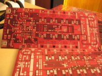
tvicol said:Here is the new PCB.
Many Thanks to andiy !!!
Regards,
Tibi
Hi Tibi!
Do you sell these?
My 405-2 is getting modded to death!
Regards
Re: Re: New PCB
Yes. PCB is 1,6mm double sided, with 70µm Cu and metalized holes. PCB's are quite large 210 mm x 91 mm.
PCB support SMD or DIL operational like LME49870 or LME49710 and a lage variety of components.
Can be made with vertical mos-fet's or lateral.
If you are interested, please see my web page and hit me a mail.
Regards,
Tibi
Patrik Floding said:
Hi Tibi!
Do you sell these?
My 405-2 is getting modded to death!
Regards
Yes. PCB is 1,6mm double sided, with 70µm Cu and metalized holes. PCB's are quite large 210 mm x 91 mm.
PCB support SMD or DIL operational like LME49870 or LME49710 and a lage variety of components.
Can be made with vertical mos-fet's or lateral.
If you are interested, please see my web page and hit me a mail.
Regards,
Tibi
Re: Re: Re: New PCB
The OP will have to be socketed DIL intially due to the never ending search for the perfect OP!
Didn't plan on using FETs, but why not! Are they used only in the dumpers, or also in the class A stage? (Any special requirements for the power supply due to the FETs?) What are the differences between vertical and lateral FETs? Which type do you recommend?
P.S: Found the photos and schematics on page 1 in the thread, and it answers most of my questions. I notice the +/-60 V supply.
Regards
tvicol said:
Yes. PCB is 1,6mm double sided, with 70µm Cu and metalized holes. PCB's are quite large 210 mm x 91 mm.
PCB support SMD or DIL operational like LME49870 or LME49710 and a lage variety of components.
Can be made with vertical mos-fet's or lateral.
If you are interested, please see my web page and hit me a mail.
Regards,
Tibi
The OP will have to be socketed DIL intially due to the never ending search for the perfect OP!
Didn't plan on using FETs, but why not! Are they used only in the dumpers, or also in the class A stage? (Any special requirements for the power supply due to the FETs?) What are the differences between vertical and lateral FETs? Which type do you recommend?
P.S: Found the photos and schematics on page 1 in the thread, and it answers most of my questions. I notice the +/-60 V supply.
Regards
Hi again Tibi!
I have re-read the thread a few times now, and have a few more questions.
1/
I would prefer the OpA to use the standard +/- 15V supply to enable easy replacement. Apart from changing the zeners, are there any problems with doing this?
2/
I would prefer to run at lower rails, around 45-50V. Any problems introduced by doing that?
3/
I was concerned by you mentioning thermal runaway for the dumpers. Is it possible to put them in class C to avoid this possibility (just like the original 405)? (I'm much more concerned about my unrepairable speakers being damaged than a little extra work for the class A stage!)
4/
I notice that you use two different symbols for grounding, but I failed to locate the resistor that splits small signal ground from power ground. How have you layed out the grounding for your amp?
Regards
Hello Patrick !
1. Change only zeners, but keep in mind that some opamps will sound better near maximum allowed voltage.
For me opamp search has ended since I found LME49870.
2. No problems with low voltage, just don't go under +/-30V
3. Thermal runaway can occur in class C as well. Bipolars will run faster. I suggest you to run this amplifier in class AB. It will sound sensible better.
4. A 10ohm resistor is between.
Regards,
Tibi
1. Change only zeners, but keep in mind that some opamps will sound better near maximum allowed voltage.
For me opamp search has ended since I found LME49870.
2. No problems with low voltage, just don't go under +/-30V
3. Thermal runaway can occur in class C as well. Bipolars will run faster.
I suggest you to run this amplifier in class AB. It will sound sensible better.4. A 10ohm resistor is between.
Regards,
Tibi
Re: Re: New PCB
Hej Patrik!
Just remember that these boards will not fit a standard Quad 405/405-2 enclosure.
Roger
Patrik Floding said:
Hi Tibi!
Do you sell these?
My 405-2 is getting modded to death!
Regards
Hej Patrik!
Just remember that these boards will not fit a standard Quad 405/405-2 enclosure.
Roger
Re: Re: Re: New PCB
Obviously!
However, I have a spare transformer and a spare case just waiting for a project!
RogerGustavsson said:
Hej Patrik!
Just remember that these boards will not fit a standard Quad 405/405-2 enclosure.
Roger
Obviously!
However, I have a spare transformer and a spare case just waiting for a project!
- Home
- Amplifiers
- Solid State
- QUASAR a reborn design