The discussion also swung to how TI and National test the distortion of these ultra-super-low distortion opamps, and this apparently is laid out in some app note. What they do is to compare what is going on at the inverting input with the input (assuming feedback is present), and analyze that residual. Kevin said that in his opinion this is a fairly variable and not totally predictable or accurate method
I think it was Peter Baxandall who showed in one of his WW articles that given a fairly small distortion to begin with, the input signal distortion is pretty much identical to the output distortion multiplied by (I believe) the closed loop gain.
The other way to measure ultra low distortion opamps is to put a smallish impedance between the two input pins to significantly lower the noise gain while keeping the closed loop gain. The output distortion rises with the increase in noise gain and can be referred back to the closed loop gain by dividing by the noise gain.
I'm waiting the arrival of my Boonton 1130 to experiment with a notch before the '400.
Jan
I find it interesting that by using fewer bits in the ADC that the distortion is reduced, compared to a DAC where in effect the converse is true. Well not exactly, but it does seem to run the other way.
Dick, sorry to hear of you health issues, hope that you actually got fixed up and had appropriate patches applied and that ur good for more miles before any scheduled shop time... hospitals suck, imo.
Ok, I did take a quick look at your pages to see what you had done.
One problem on the QA is that the frequency of the oscillator is adjusted to fit the software's bins and also the sinewave is not continuous. So, it's unclear to me that one gets the full performance of the QA using an external oscillator, but perhaps.
Wondering why you would not use the QA's oscillator, and which oscillator do you generally prefer? The QA oscillator is fairly high quality... I hope to test it this weekend on the 7725, assuming I can find the box to check in the menu to make it run continuously.
So the next thing that comes to mind is that since the DUT's signal has to pass through the opamps of the notch, how does that effect the distortion products, or does it? Does one need or want very high performance chips here? In effect the passband, "un-notched" area is just a follower - or is there some gain? Or are we assuming that the added distortion of the notch's active devices is there but adding to a residual signal that is already -1XXdB down so the addition to that signal is essentially meaningless?
Just trying to follow the opera along in the libretto.
_-_-
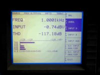
QA Oscillator alone
I did a very fast check of the QA oscillator.
It is set to the default of 1kHz and 0dB.
The VP-7725 shows almost nil 2nd order! Look at the image.
This was one of the best readings I got, it bounced slowly up and down, going up about 5-6dB.
Important to note this is with both instruments *cold* as in outside temp, which was about 55-60deg F. Thinking the QA works better *cold*.
I also did a loopthrough on the QA. Best readings I have ever gotten thus far. Noise floor happened to be in the -135dB range.
So, I think we can safely conclude that at least the 2nd order spurs in the QA are not from the internal oscillator.
There is some uncertainty however, as setting the level lower than 0dB in the continuous run oscillator dialog box did not produce a signal that the VP-7725 was able to read. I did not put a scope on it to confirm what was coming out of the QA, but loopthrough said it was working fine at that level. (at least I think it did, it may be that I imagined this, as the RUN button probably pulls the continuous feature off) This is part of the uncertainty of operating the VP-7725, it is difficult to know what it wants or what it is really doing at any given point - you hear relays clicking, but it's not clear why or what they are doing. It's unclear that there are not one or more faults either.
I also explored the hitherto unknown "Notch" menu. It shows "AUTO" - so apparently there is an automatic notch applied. If there is a way to take it off AUTO, I could not find it. Another situation where a manual would be nice.
Probably will find one by the time its performance has been equaled by a $99 LSI affair...
Attachments
Last edited:
I found there is a threshold that the input must be higher than in order for the internal auto test system to work. Being this is basically for production testing that is OK. Seems to be looking for a 1v input, I recall.
Let me/us know if you figure out what the Notch is used for... or why display it is on auto mode.
It is interesting that the 4 and 5th Harmonics are growing... maybe higher Harmonics continue to grow as well? This is unlike the analog osc which 2-3H dominate and higher orders are much lower.
-RM
Let me/us know if you figure out what the Notch is used for... or why display it is on auto mode.
It is interesting that the 4 and 5th Harmonics are growing... maybe higher Harmonics continue to grow as well? This is unlike the analog osc which 2-3H dominate and higher orders are much lower.
-RM
Last edited:
For which unit - the auto ranging threshold?? This with other than the 7725?
Next chance I get I will push a lot of buttons?? See what happens.
I am presuming that the notch is applied similarly to the SR-1...
As of now I can't figure out how to get a whole bunch of stuff to do anything.
There is a keypad for example, with buttons to their right. No idea how to make it do something.
Also one can take the range out of AUTO, and select a manual level, but it doesn't seem to "stick" - there must be another button to push... very mysterious.
Yes, I was surprised to see 2H so low!
But it does serve to indicate that the 2nd harmonic spur in the display of QA is not being generated by the oscillator, so that is almost certainly off the table now.
Next chance I get I will push a lot of buttons??
See what happens.I am presuming that the notch is applied similarly to the SR-1...
As of now I can't figure out how to get a whole bunch of stuff to do anything.
There is a keypad for example, with buttons to their right. No idea how to make it do something.
Also one can take the range out of AUTO, and select a manual level, but it doesn't seem to "stick" - there must be another button to push... very mysterious.
Yes, I was surprised to see 2H so low!
But it does serve to indicate that the 2nd harmonic spur in the display of QA is not being generated by the oscillator, so that is almost certainly off the table now.
But they were notching the fundamental with about 40-50dB (iirc) of analog notch and (again iirc) about 70dB of digital notch, and then the software "knows" this and stacks that onto the scale for the apparent range. If I have that part reassembled properly.
What is the digital notch good for, other than saving a dozen of bits
for the DSP, if anything?
After the ADC, it's only massaging numbers.
BTW. Can the QA400 do Bode plots (amplitude & phase)?
I don't dare to ask for cross correlation.
regards, Gerhard
gerhard, Kevin McKee of SRI claimed that the combination permitted them to measure a much greater dynamic range, get better S/N when measuring harmonics. I am only reporting what he said. You could just email him and see what he says?
When I walked over and actually *looked* at the display it was showing stuff at -240dB!! That is what set off the discussion... as in "is this real"?
When I walked over and actually *looked* at the display it was showing stuff at -240dB!! That is what set off the discussion... as in "is this real"?
QA400 frontend
Looking for more information about the QA400, I found this project.
Not only found more details about it. But it seems very interesting.
OSH Park ~ Profile for prettygoodaudio
Looking for more information about the QA400, I found this project.
Not only found more details about it. But it seems very interesting.
OSH Park ~ Profile for prettygoodaudio
Yes, but I have not figured out how to order, if one wanted to. Maybe you have to create an account first? In particular it's unclear how much the board would cost... and they seem to say that they make a "panel" of them to drop the cost, so maybe they are pre-made?
Also in a very fast look, did not see what the power supply might be... and if there is any text documentation...
_-_-
Also in a very fast look, did not see what the power supply might be... and if there is any text documentation...
_-_-


Yes, but I have not figured out how to order, if one wanted to. Maybe you have to create an account first? In particular it's unclear how much the board would cost... and they seem to say that they make a "panel" of them to drop the cost, so maybe they are pre-made?
Also in a very fast look, did not see what the power supply might be... and if there is any text documentation...
_-_-
It seems that you need to order multiples of 3 at 28.70 each.
http://oshpark.com/ said:Your design will cost $86.10 per set of three
The questions are, will it work
will we start a group buy (we need to split up these sets of 3) who is 'prettygoodaudio' and will he support his design (preferably on this site at a dedicated builders forum).And last but not least, there is the work of '1audio' will this be a buildable project, and will we prefer it (I do until proven otherwise
)I found the forum and the developer's interface.
QuantAsylum QA400 Audio analyser
It is a simplified version of that other interface.
Audio test interface
QuantAsylum QA400 Audio analyser
It is a simplified version of that other interface.
Audio test interface
This bears some more investigation before jumping to "group buy" status.
Don't forget the power supply requirement too...
Also, it's entirely unclear how many lurkers here have bought or will buy the QA400, and so the interface board.
Not to throw cold water on this, so far my ultra simple pair of metal film resistors in a box/inline with the input has worked just fine for every day measurements on power amps. Yes, not calibrated, but sufficient for amps that do not get down into the -110dB sort of residuals. Anyhow, an interface that provides range calibration to me is more valuable than one that is not.
the designer writes in the other forum:
"Input noise is below -97 dBu, THD immeasurable with my current set-up"
and:
"I've submitted the ATI to the AP. Performance is up to expectations:
Frequency response <5Hz-200+kHz BW (+0,-0.5dB)
EIN of the measurement section better than -103dBu@unity gain, -88@20dB gain (22Hz-22kHz BW)
THD+N better than 0.0035% from 20Hz to 20kHz (measurement BW 30kHz)
Residual noise of generator section -108dBu @ 0dB attenuation (22Hz-22kHz BW)
The only performance point I had not been capable of predicting was the real capability of the circuit to drive unbalanced sources with the attenuator in-circuit. Unlike a xfmr-output, the 1646 has a finite CM impedance, which alters the level when on eof the legs is shorted to ground.
I have found this difference to be less than 0.2dB for 50r and 150r output Z, and less than 0.5dB for 600r output Z."
then:
" I just ASSumed he was talking output not input noise. -108 @ 20dB gain vs -103 @ unity seems reasonable for the input side."
JR
"Yes, sorry. EIN is -108@20dB gain"
Last edited:
Sometimes it's hard for me to focus on the interface, too many other problems running and interlaced vying for my limited brain processing cycles...
But there are two separate and distinct cases for the interface to deal with:
- signals that are low and need gain
- signals that are too high and need attenuation
And the main aspect: QA front end blow up protection.
(skipping the issue of balanced vs. unbalanced entirely)
But there are two separate and distinct cases for the interface to deal with:
- signals that are low and need gain
- signals that are too high and need attenuation
And the main aspect: QA front end blow up protection.
(skipping the issue of balanced vs. unbalanced entirely)
Sometimes it's hard for me to focus on the interface, too many other problems running and interlaced vying for my limited brain processing cycles...
But there are two separate and distinct cases for the interface to deal with:
- signals that are low and need gain
- signals that are too high and need attenuation
And the main aspect: QA front end blow up protection.
(skipping the issue of balanced vs. unbalanced entirely)
Yes, I do agree, but the balanced issue is also important
I would like to do many measurements floating with respect to ground (mainly VAS and Cascode issues in power amplifiers).The VP-7725 shows almost nil 2nd order! Look at the image.
This was one of the best readings I got, it bounced slowly up and down, going up about 5-6dB.
So, I think we can safely conclude that at least the 2nd order spurs in the QA are not from the internal oscillator.
This is one of the issues I have found and been trying to address..... the variable level of uncertainty for the 2H -- those closest to the notch filter. Phase affects can add or subtract from the 'true' value of the 2H. In your case you have an uncertainty spread of 5-6dB. That is too much for accurate use. especially at Harmonic levels which are below -100dB where accuracy is worse.
And, at levels below-100, you can also find that the 2H level varies with the input level...3H not so much variation (further from the notch effects on it). The variation is almost as much. So that produces a total variation below -100 which is just guessing and cannot report much of anything below -100 as a Fact.
Keeping the range between -10 and -100 it is accurate enough to use and quote figures/data/numbers with some confidence. So, you Must use a notch filter to keep everything within a -90 db dynamic range or less.
I notice that many sound cards and the like are not as precision as test equipment and there are a number of specs which are lacking for using them as test equipment core. One is there is no spec on the accuracy of the measured 2H.
The Panansonic brand of test equipment includes specs on the accuracy of their measured 2H as +/- 1dB. So, this uncertainty issue with some designs is understood and designed out.
["Second harmonic accuracy: +/-1dB (20 hz to 20.09 kHz). +/- 3dB all ranges"]
In the test equipment world, accuracy is most important and we need to know the accuracy of an ADC for audio and being used for test equipment. Or characterize it and correct for it -- maybe in a look-up table so data is automatically corrected.
Fortunately, I found better test equipment and can use it to compare against. But the sound-card and QA400 etc are really great if, as has been noted, you dont expect to need accuracy below -100 and can keep the input within a more limited window.
Thx-RNMarsh
Last edited:
RNM,
One reason that I am trying to find the manual for the VP-7725 is that I question its present state of affairs. I am not certain that it is behaving as it should, and/or if it meets specs or not. It well may.
As far as all this regarding the notch, I would expect that at an octave out well designed high Q notch filters ought to have pretty nearly nil phase angle and pretty flat in amplitude?
Perhaps you can help here, just how deep of a notch is required to get another 20db of measurement range out of the QA? That would give a usable range of ~-120dB which would be excellent.
The other question that I did not see an answer to, and on this I have nothing to draw upon, is a notch required or is a very steep HP function sufficient??
_-_-
Last edited:
- Home
- Design & Build
- Equipment & Tools
- QuantAsylum QA400 and QA401