The whole box on the QA401 is isolated from USB and the host PC. Putting in on a PC chassis may couple both electrostatically and magnetically. The cables supplied are not the greatest. I had problems with connections as well.
Obvious fix: keep the QA401 away from things that cause interference. That would include anything with a switching supply (even phone chargers) and anything with a power transformer. It will work with a longer USB cable. Just make sure the cable has big power conductors or use a powered USB hub close to it.
Obvious fix: keep the QA401 away from things that cause interference. That would include anything with a switching supply (even phone chargers) and anything with a power transformer. It will work with a longer USB cable. Just make sure the cable has big power conductors or use a powered USB hub close to it.
Hazardous Environment
Hello,
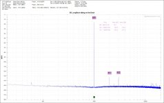
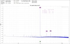
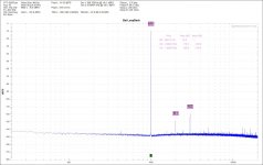
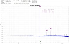
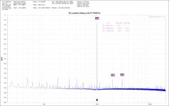
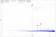
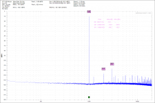
I have played with this QA a little more this morning. The quick start guide recommends -16 dBFS as the sweet spot for the generator output. See the attached FFT’s of SE connections on the desk and on top of the PC. Also see the attached FFT’s of Balanced connections on the desk and on top of the PC.
There is one more attachment showing the QA with SE connection sitting on top of the PC PWM (chopped up DC) controlled cooling fan.
I get the impression that the inside of a PC is a hazardous environment for a sound card.
DT
Hello,
I have played with this QA a little more this morning. The quick start guide recommends -16 dBFS as the sweet spot for the generator output. See the attached FFT’s of SE connections on the desk and on top of the PC. Also see the attached FFT’s of Balanced connections on the desk and on top of the PC.
There is one more attachment showing the QA with SE connection sitting on top of the PC PWM (chopped up DC) controlled cooling fan.
I get the impression that the inside of a PC is a hazardous environment for a sound card.
DT
Attachments
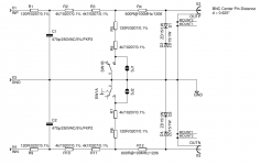
Can somebody please measure the BNC-centerpin-distance between + and - Inputs/outputs of a QA401? (In mm please. I guess/it might be 25.4mm but you never know!)
I'm still waiting for my unit to arrive, but I wanted to start designing a matching attenuator PCB this weekend")
Thanks!
I'm still waiting for my unit to arrive, but I wanted to start designing a matching attenuator PCB this weekend
Thanks!
Can somebody please measure the BNC-centerpin-distance between + and - Inputs/outputs of a QA401? (In mm please. I guess/it might be 25.4mm but you never know!)
I'm still waiting for my unit to arrive, but I wanted to start designing a matching attenuator PCB this weekend
Thanks!
Hello,
Within my ability to measure in decimal inches and multiply by 25.4 mm/in, they are 16mm center to center, top+ to bottom-.
DT

For those interested in the Autoranger: I just posted an update to the project status here:
http://www.diyaudio.com/forums/equipment-tools/299635-autoranger-soundcards-5.html#post4920180
Jan
http://www.diyaudio.com/forums/equipment-tools/299635-autoranger-soundcards-5.html#post4920180
Jan
Since this is made in USA, could the dimension be an inch size?
5/8ths of an inch is 0.625" =15.875mm
or 6/10ths of an inch =15.24mm
Thanks for the hint! I'm still used to design all my PCB-related stuff in fractions of Inches, therefore 0.625"/18.875 is my choice anyways. Probably I should not have asked for mm specificly - in order to avoid all this units-confusion
assuming you are feeding into a high impedance measuring instrument, I get an attenuation of -9.47dB. 20log({120+4700}/{120+4700+4700+4700+120})
What impedance did you assume as the load?
600ohms, or 100k, or 10M?
The load impedance for any of these attenuators is very important if you require accurate measurements. And needs to be stated at the output terminal/s
What impedance did you assume as the load?
600ohms, or 100k, or 10M?
The load impedance for any of these attenuators is very important if you require accurate measurements. And needs to be stated at the output terminal/s
I would prefer multiple tappings into a ladder attenuator.
Top tapping just adds the resistor string in parallel with the measuring instrument impedance (somewhere between 1M and 10M).
If you wanted a 1/10th output the resistor string would be 9X and 1X for the two resistor, provided the 1X <<< than the loading impedance
eg set X to 100r,
therefore 1X = 100r and this is in parallel with the 1M loading impedance.
set 9X to 900r.
The attenuation is [100r||1M]/[900r + {100r||1M}]
and because Zout ~100r and is <<< 1M, the measurement is reasonably accurate (-0.009%).
Substitute other numbers to investigate the effects on measurement accuracy.
A good way to get an accurate 9:1 ratio is to use a Hamon divider
With care this Hamon could be the most accurate instrument you can ever assemble.
Last edited:
DT - Thanks for the post. That looks good also. I sent a question to QA a while ago but did not get a response so I'm wondering about their responsiveness. Any thoughts?
Also, do you know if they are planning on writing an ASIO driver so that the QA401 could be used with other software?
Thanks,
Joe
Also, do you know if they are planning on writing an ASIO driver so that the QA401 could be used with other software?
Thanks,
Joe
RCH is Red Curly Hairs.
Hello,
To clarify the cognitive process, the two BNC’s are tightly stacked over under. The lock washers under the nuts that hold the BNC’s to the front panel touch each other. I got out my trusty Stanley rule and measured a couple of RCH’s over 5/8 or 0.625 center to center. RCH is Red Curly Hairs. I added 0.005” to 0.625” and called it 0.630” total. 0.630” * 25.4 mm/inch equals 16.002 mm. So within my ability to measure the spacing between the BNC’s is 16mm.
jpalovic, I traded a couple of emails back and forth with QA, they were responsive to my questions after I had made the purchase. I have no idea about the ASIO driver question.
DT
Thanks for the hint! I'm still used to design all my PCB-related stuff in fractions of Inches, therefore 0.625"/18.875 is my choice anyways. Probably I should not have asked for mm specificly - in order to avoid all this units-confusion
Hello,
To clarify the cognitive process, the two BNC’s are tightly stacked over under. The lock washers under the nuts that hold the BNC’s to the front panel touch each other. I got out my trusty Stanley rule and measured a couple of RCH’s over 5/8 or 0.625 center to center. RCH is Red Curly Hairs. I added 0.005” to 0.625” and called it 0.630” total. 0.630” * 25.4 mm/inch equals 16.002 mm. So within my ability to measure the spacing between the BNC’s is 16mm.
jpalovic, I traded a couple of emails back and forth with QA, they were responsive to my questions after I had made the purchase. I have no idea about the ASIO driver question.
DT
Last edited:
For those interested in the Autoranger: I just posted an update to the project status here:
http://www.diyaudio.com/forums/equipment-tools/299635-autoranger-soundcards-5.html#post4920180
Jan
Linear Audio Vol 12 is out! Autoranger and SilentSwitcher
Jan,
None of your links are working today.
DT
What is the goal of the atteuator? The circuit is pretty complex. You can do the same with a tesistor and a trim cap.
The max in is 30V for the QA401. If you are measuring amps you need a load resistor. You can incorporate a.tap in a load to reduce the voltage.
Ill post more on this later.
Sent from my LG-H811 using Tapatalk
The max in is 30V for the QA401. If you are measuring amps you need a load resistor. You can incorporate a.tap in a load to reduce the voltage.
Ill post more on this later.
Sent from my LG-H811 using Tapatalk
- Home
- Design & Build
- Equipment & Tools
- QuantAsylum QA400 and QA401