Kei - quote by chance I am in the process of building some 606 replicas initially just one to see if it works out ok!
Years ago I built a few copies of the original 405 from the article published over 20years ago in Wireless World and they worked fine, and now I am about to embark on some new speakers - Linkwitz Orions that require at least 4 amplifiers per channel.
So initially I am building one as a proof of concept and will use it to power a home theatre sub-woofer, but am curious -since it seems to me that significant power is passed through the 1.5uH choke are you using a commercially available one, or are you winding your own?
In days gone by I did build my own, but back then I had access to test equipment to measure the coils, I guess I could knock up a Maxwell Bridge and roll my own, but wondered are you using a commercially available inductor?
Anyway wrt to your question regarding gain - I think you might find some interesting articles on this site Home -a QUAD specialist site where you will find a more elegant method of normalising the gain.
Cheers
Ed
Spent the past 2 days reading up on this ground plane and its purpose. It seems it was introduced on issue 3 pcb's to help reduce interference from other appliances.
Here's what the service manual states for modifications:
(9) June '87 (SN 4500 approx) Shorting link of 16 SWG (1.5mm) tinned copper wire connected across PCB track earths. (see page 13) 330nF (C330NXA) capacitor C20 fitted across mains transformer primary. To reduce interference from electrical appliances (thermostats etc.)
(10) November '87 (SN 5700 approx) PCB iss. 3 introduced to improve screening and reduce interference from electrical appliances. R14, R15 and CR1 taken to R20 and R26 supply rail to improve performance.
Page 13: Fitting link to Issue 1 & 2 PCB
Mod 9 In cases of interference from household appliances, thermostats etc, connect a link across the track side of each amplifier printed circuit board as shown below.
(a) Scratch the protective lacquer from each PCB at the two points marked 'O' adjacent to 'C9, R3' and 'IN' respectively, and connect an insulated piece of 16 swg (1.5mm) tinned copper wire between these points as indicated.
(b) For very severe cases a 330nF 250V AC working capacitor (C20) may also be connected directly across the mains transformer primary connections.
These modifications were incorporated in production models with issue 2 PCB, from S/No 4500.
Wouldn't it be possible to just add a track like the attachment or is that poor design. If the track is not a good solution, is the quad wire mod any better?
Presumably the idea is to reduce the loop area formed by the ground wires and the core of the amplifier circuit. If so, then your modified PCB is better than the original, the wire modification is better yet (because the ground wire passes straight under the core of the amplifier circuit) and the ground plane PCB is best. I have no idea what is acceptable for you, though. Are there any refridgerators and/or AM transmitters nearby?
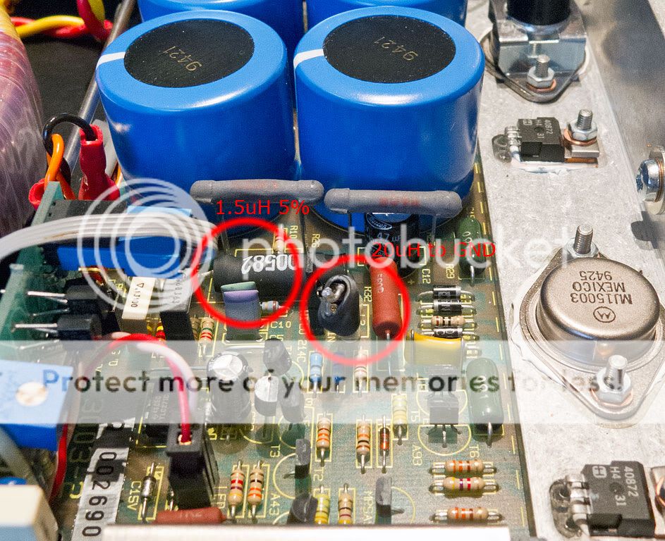
Ed, i've listed a commercial part for the inductors as the service manual states that the coils should be 5% tolerance. (i'm not sure if i could wind my own to be that accurate without a tool for measuring it, as none of my meters can measure inductance.) This is the 1.5uH part i've listed.
I have no interference issues with any of my other devices so in principal i may be ok without it or i could add the wire. (i'd rather have a single sided pcb as its far easier to make.)
I have no interference issues with any of my other devices so in principal i may be ok without it or i could add the wire. (i'd rather have a single sided pcb as its far easier to make.)
Last edited:
Assuming that you use a coil without a core of a magnetic material like iron or ferrite, self heating presumably limits the allowable current. The DC current rating then has to equal the maximum RMS output current. With sine wave drive and resistive load, you can calculate that from I=sqrt(P/R), where P is the output power and R the load resistance.
The DC resistance affects the output damping factor and the balance of the distortion cancelling bridge. There is probably some optimum value that gives minimal distortion, but I know no simple way to calculate it. It is probably very low indeed, so the Bulgarian coil sounds OK.
Kei,Marcel,Stuart - the dc resistance was where I was coming from - seems a little high and the max current capacity of that inductor is only 0.67A.
When I previously built 405 clones I made my own, but back then I worked for Marconi so had access to proper test gear. It should be possible to build your own wound over a high value resistor body and check using a Maxwell Bridge (similar to Wheatstone) - where you only need a reasonable DVM, sig gen and high tolerance R and a C-the formula reduces the calc of the inductor value to R1 * R2 *C - so freq/voltage not important (as long as the bridge balances")
When I previously built 405 clones I made my own, but back then I worked for Marconi so had access to proper test gear. It should be possible to build your own wound over a high value resistor body and check using a Maxwell Bridge (similar to Wheatstone) - where you only need a reasonable DVM, sig gen and high tolerance R and a C-the formula reduces the calc of the inductor value to R1 * R2 *C - so freq/voltage not important (as long as the bridge balances
I don't think my dad would appreciate me dismantling his 240 to unwind L3. I believe i might have access to a meter that measures inductance so i could test out the ф10mm/17.5 turns/1мм² ≤ 0.03Ω theory.
What about the other inductors then, should they also be home made or would a commercial part be ok? (L1 20uH & L2/3 2uH 10%)
What about the other inductors then, should they also be home made or would a commercial part be ok? (L1 20uH & L2/3 2uH 10%)
20% tolerance where quad suggest 5%. The tolerance seems to be the sticking point for finding a commercially available part.
This one seems reasonable.
This amplifier is rated at 140W into 8ohms
This one seems reasonable.
This amplifier is rated at 140W into 8ohms
Last edited:
Ok so probably wind your own is the best route since that part is only rated at 1.8A which means it's overloaded at I^2R 25W into an 8 ohm load :-(
Also the 606 Service data manual states the rated output current peak is 12A so spending a lot on a very nice low impedance PSU and not beefing up this component could lead to disappointment, or premature component failure...
Also the 606 Service data manual states the rated output current peak is 12A so spending a lot on a very nice low impedance PSU and not beefing up this component could lead to disappointment, or premature component failure...
Had a look at the 240 which appears to use the same parts. Have to admit that the inductor doesn't seem particularly big. The only problem i can see with making it yourself is you won't know what current it can pass.
According to my calculations at 140W into exactly 8 ohms we will have 4.2A out. (which is certainly more than most of those inductors can handle) I know the service manual states 12A max current output, but this equates to over 1KW into 8 ohms or 576W into 4 ohms. Seems like overkill to me as there's no way the other components in the system would handle that, but i agree that we need something that is at least able to handle the 140W output. (5A+ should cover it)
An externally hosted image should be here but it was not working when we last tested it.
According to my calculations at 140W into exactly 8 ohms we will have 4.2A out. (which is certainly more than most of those inductors can handle) I know the service manual states 12A max current output, but this equates to over 1KW into 8 ohms or 576W into 4 ohms. Seems like overkill to me as there's no way the other components in the system would handle that, but i agree that we need something that is at least able to handle the 140W output. (5A+ should cover it)
That's RMS not peak current - sure maybe a 5A capable choke is acceptable.
I am pretty sure that the bridge values Quad used were somewhat of a compromise, and thus a commercial 20% tol dev may be ok - I'll need to re-read the original 1975 document that detailed the calculation, will try and look at this tonight.
I am pretty sure that the bridge values Quad used were somewhat of a compromise, and thus a commercial 20% tol dev may be ok - I'll need to re-read the original 1975 document that detailed the calculation, will try and look at this tonight.
I reckon that's the way to go for all the inductors
wrt to current capacity - bear in mind that speaker impedances are nominal values so even if marked as 8 ohm may well dip to 4 or below over the audio spectrum. At least with a 'beefy' inductor for 2,3,& 4 the amplifier will present a lower impedance to the load, and control it better
wrt to current capacity - bear in mind that speaker impedances are nominal values so even if marked as 8 ohm may well dip to 4 or below over the audio spectrum. At least with a 'beefy' inductor for 2,3,& 4 the amplifier will present a lower impedance to the load, and control it better
- Home
- Amplifiers
- Solid State
- Quad 909 Clone