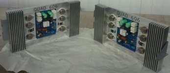
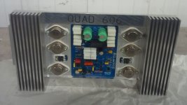
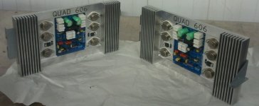
I used the calculator and it said the coil I made was 1.2uF so I wound an new larger one. 27 turns, .35" and 1.3" long with 18ga enameled wire. Exactly the same square waves as before. The J503's cleared Frisco so I should have them tomorrow or the day after. It will be interesting if they make a difference.
Blessings, Terry
Blessings, Terry
Hi again. Yes, I read #443 earlier and I see what you meant about the square wave response - the FR is indeed falling all the way from HF down to LF. That really is a problem but I think it will have a simple solution in the feedback equalization (I should have used that term instead of compensation earlier). I doubt the J503 current limiting "diodes" will solve this but I've been wrong before too! Here's hoping.
hi.
I have also built this clone of 606, and have read on the sidelines, so I was a little curious about how my own amp measured and to my surprise my amp measured the same as terry's amp with square waves in the low frequency end from about 200hz and down the square was bad on the scope, but when connecting a sine wave there is no drop in the low frequency when i turn the frequency down i can not see any drop on the scope.
maybe I am wrong or i missing something but should the sine wave like the square also drop in amplitude if the amp cut off in the low end when i turn the frequency down???
maybe im wrong again, but maybe this amp dont like square waves...
LS
Hi LS,
Thanks for doing that. This will end my search for errors. The square form isn't suggesting that there is a drop in power. That shape is described as how it would look with a high pass filter in place. It changes the harmonics of the pitch. The center of the pitch is still there but the lower harmonics are rolled off while the upper harmonics are accentuated. The upper frequencies show the opposite which would indicate there is a low pass filter as well. This explains to me why the amp tends to be more prominent in the mid range than most of my other amps. It sounds just fine and the only way yoou would probably every notice it is in a blind A/B test. I am happy to know that the device substitutions I made didn't play a part in it.
Thanks again, Terry
Hi Ian,
If you take a look at post #442 you will see I posted scope shots of the amp with an even voltage input at various frequencies with an 8ohm dummy load. It is set to produce about 10vac at the output. I didn't bother showing 20hz because 100hz was tilted enough to make the point. You can also see that it starts getting rounded at 10k so it pretty much shows what I am hearing which that it is voiced in the midrange area. I'm not saying that is bad, it is a nice sounding amp. I'm just reporting what I see and hear for the benefit of the thread and to see if maybe I have something that needs to be changed. Others may want to build the amp and it never hurts to have information.
Blessings, Terry
Hi Terry, Square waves typically require 10X the bandwidth of the fundamental to look good, so unless you have a very wide bandwidth amp we would not expect a 10 KHz square wave to look so good. There have been many amps were the goal is very wide bandwidth and those produce nice square waves, but they are also more vulnerable to RFI. Some British amps tend to go for just enough bandwidth rather than the max, and this is probably one of them.
If you drive it to 1 or 5 W out it would be good to find the - 1 dB upper and lower frequencies as well as the - 3dB. This tells you the small signal bandwidth. Some amps don't like being driven to full power above say 20 KHz so be careful if you decide to try higher power. I doubt that there is anything wrong with the amp but certainly check the frequency response.
Small inductors should never have any impact on bass, more likely it is the input cap size, feedback loop, or the VAS bootstrap cap if it has one. Try making the input cap 10X bigger.
Which schematic did you build it from?
If yours is like the schematic in OP here, then the input cap is 330nF and the load is 62K, you can plug those into this calculator:
(Sample)RC Low-pass Filter Design Tool - Result -
and the - 3dB point is calculated as (Fc) = 7.78 Hz which is not very low for a solid state amp. I really suggest that you try plugging them in, it will help take some of the mystery out of amp design.
Multiply the cap value by 10 to 3.3 uF and you'll lower Fc to .778 Hz.
Obviously, the fundamental of a 20 Hz square wave is above 7.78 Hz but it is the phase shift that alters the shape of the square wave by moving the harmonics relative to one another. I'd probably up the bootstrap cap, C7 in the OP schematic, by 10X just to scale everything.
Similarly R1 and C1 in the first post form a low pass filter, and you could reduce the cap to raise the - 3dB
frequency but this amp has a lot of compensation with inductors etc. so I probably wouldn't risk that. If you
don't mind the risk you might lower the cap to 100 pF.
This is commonly done, the HK Citation 12 was nearly identical to the RCA quasi comp reference design but the input cap
and a few others were about 10 - 20 times larger. It made decent square waves.
Last edited:
Just off the top of my head, C7 looks too small relative to the small value, 560 ohm, resistors used. I wonder if this was done to limit the LF power for use with electrostatic speakers that have poor LF power handling.
I thought I SPICE simulated this several years ago but I can't seem to find it if I did.
I thought I SPICE simulated this several years ago but I can't seem to find it if I did.
I don't push an amp with square waves. I normally set it to 10vac output. I have burned sobel resistors before so I take it easy. I don't put a lot of store in them but they do give an idea of how the amp is working. I'm sure it is just in the filters. I followed the recommended values so I have to believe that this is what the designer was shooting for. It was a fun build. I thank Juan Vargas for the inspiration.
Blessings, Terry
Blessings, Terry
hi there ... i know this thread is old but i followed all of it ... can any one othe builders of this project summarize the required mods for the good quality stable output!!!
or if some one has applied this mod to the pcb layout it self so only install the components and run?
or if some one has applied this mod to the pcb layout it self so only install the components and run?
Hey Terry I might be wrong but on the simulation I did not have a CR2 J503 and what I did I use a simple 1N4148 and on the simulation responds really well
can you give me the ms* file for quad 909 ?
thank you
can you give me the ms* file for quad 909 ?
thank you
I'm wondering, why is the 405 so popular to clone while i havn't seen any 909 clone yet.
I'm keen to buildf this version, but i'm going to be in more money then buying a second hand one (atleast that's what i think)
Am i correct?
Hi, I found a gross error in the circuit board. R3 must be connected to the cathode of D1. Everything else is fine, great job.³roger that Andrew,
I will leave a file Sprint 6 here if some one need to make a clone of the Quad 909 "not to be commercialized please" only to diy and learn about this current dumping design, from the data that was post here I was able to re-clone the PCB but to let you know it might not be as accurate as to fit the original heat sink so the heat sink has to be made for this clone PCB unless holes of the TO-3 are enlarged to have some sort of game tweaking but not recommended I thinkon the grey layout image what I did is flip the image so I will have a top view of the components then I used a back wall on Sprint file then I begin from there making the components from scratch and then I place the copper traces little bit at the time I spend probably 3 day
doing this well I hope some one check this for bugs please if any error you might see feel free to post it here I do not mind at all

Best Regards
Juan
Eagle design files?
I have the full set of design (including the .sch and .brd) files copied many years ago from the original Bulgarian site. The site now requires registration to access it and I can't seem to register properly (the anti-bot question seems to need an answer in Bulgarian...). Although the files open in the hobbyist version of Eagle (v9.6.2), when exporting as a Gerber file there''s an error message related to "N$5" and an invalid polygon, and the export fails. Anyone have a "clean" set of these files?
I have the full set of design (including the .sch and .brd) files copied many years ago from the original Bulgarian site. The site now requires registration to access it and I can't seem to register properly (the anti-bot question seems to need an answer in Bulgarian...). Although the files open in the hobbyist version of Eagle (v9.6.2), when exporting as a Gerber file there''s an error message related to "N$5" and an invalid polygon, and the export fails. Anyone have a "clean" set of these files?
- Home
- Amplifiers
- Solid State
- Quad 909 Clone


