Hello Terry
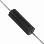
I found this fix inductors they already have the correct value
DN7711-ND 1.5uH 5.6A
2474R-03L API Delevan Inc | DN7711-ND | DigiKey
M8268-ND 4uH 8A
5230-RC Bourns Inc. | M8268-ND | DigiKey
I'm not sure if the original coil have "ferrite" material
I found this fix inductors they already have the correct value
DN7711-ND 1.5uH 5.6A
2474R-03L API Delevan Inc | DN7711-ND | DigiKey
M8268-ND 4uH 8A
5230-RC Bourns Inc. | M8268-ND | DigiKey
I'm not sure if the original coil have "ferrite" material
Attachments
Hello Terry
I found this fix inductors they already have the correct value
DN7711-ND 1.5uH 5.6A
2474R-03L API Delevan Inc | DN7711-ND | DigiKey
M8268-ND 4uH 8A
5230-RC Bourns Inc. | M8268-ND | DigiKey
I'm not sure if the original coil have "ferrite" material
Thanks Juan,
Those look pretty neat. I'll order some.
Blessings, Terry
I did not follow this thread from beginning, but I think that could be good idea to read about current dumping amps, the quality and exactness of the inductor is very important here, it is not used to protect from a capacitive load.
Sorry if I intrude in this thread with the things already clear to all participants.
Damir
Sorry if I intrude in this thread with the things already clear to all participants.
Damir
I would strongly recommend to stay with air core. The cored ones might saturate at high levels which will be far worse than few % off exact value. Just be sure you will use wire thick enough. Some 1.2mm will probably do the job here. There was some discussion here already. KatieandDad is the guy to ask about it. He made some really nice ones.
And yes, Dadod is absolutely right, coils are important here. But again few % off probably won't cause disaster. Certainly not big difference in sound.
Cheers
And yes, Dadod is absolutely right, coils are important here. But again few % off probably won't cause disaster. Certainly not big difference in sound.
Cheers
Agreed. There are many types of ferrite, most types used now are for blocking EMI or for SMPS duty and there can be serious problems with audio frequencies. The problem being that the inductor service duty isn't specified and often datasheets don't specify adequately either.
Here's the calculator suggested earlier and of course, there's a single layer coil type on the same site: Pronine Electronics Design - Multilayer Air Core Inductor Calculator
Here's the calculator suggested earlier and of course, there's a single layer coil type on the same site: Pronine Electronics Design - Multilayer Air Core Inductor Calculator
I would strongly recommend to stay with air core. The cored ones might saturate at high levels which will be far worse than few % off exact value. Just be sure you will use wire thick enough. Some 1.2mm will probably do the job here. There was some discussion here already. KatieandDad is the guy to ask about it. He made some really nice ones.
And yes, Dadod is absolutely right, coils are important here. But again few % off probably won't cause disaster. Certainly not big difference in sound.
Cheers
I have been looking at images of what I believe are genuine Quad boards, and they don't appear to use air core units.
As for the bass response, I wonder if those of you who have working models of this amp could hook one up to your scope and run some square waves through it and see if you see what I see. I hate to be chasing demons that don't exist. The amp sounds fine and the sonic signature may not be noticed if not in a A/B setup like the one I use.
Blessings, Terry
Hey Terry
Yes I know. Original coils are cored ones..but as Ian pointed out just to know that isn't enough. There are many different ferrite materials with really different characteristics. And again as Ian pointed out most are used to block EMI etc...With air core you ''are safe'' as long you have wire thick enough. It is safe choice.
Sadly I can't put mine on scope since it is not mine any more. It belongs to pianist from national philharmonic orchestra now...he was really all about ''I want that amp''...and so I give it away
Have you tried let's say 20-30Hz sine wave? And with signals over 20kHz be careful. You will probably at least fry output zobel.
Cheers
Hey Terry
Yes I know. Original coils are cored ones..but as Ian pointed out just to know that isn't enough. There are many different ferrite materials with really different characteristics. And again as Ian pointed out most are used to block EMI etc...With air core you ''are safe'' as long you have wire thick enough. It is safe choice.
Sadly I can't put mine on scope since it is not mine any more. It belongs to pianist from national philharmonic orchestra now...he was really all about ''I want that amp''...and so I give it away
Have you tried let's say 20-30Hz sine wave? And with signals over 20kHz be careful. You will probably at least fry output zobel.
Cheers
I did a full array of sine waves. They all look the same. It is the square waves that tell the tail on frequency strength. If you look at post #442 you can sehat they look like. I is pretty clear that the low end is a bit lacking. I just read back through the thread and the OP actually used similar devices to the ones I used. I should probably swap out the 2N5xxx's for the MPSA42/92 and at least see if there is a difference.
Again, the amp "sounds" fine. It just has a more prominent midrange that most of my other amps. Would be great for surround systems where voices tend to get lost in the mix.
Really, I can leave it as is. I just wanted to hear from someone who has a scope and the amp and could take a few minutes and run some square waves through it so I would know if I need to keep working at it or if it is just working to spec. It is sidelined right now until the parts arrive. Once they are here I will get it back on the bench and do some more.
Blessings, Terry
Hey Terry,
I doubt that swapping transistors will change anything. Only thing which probably will make same difference is installing proper current sources (j503).
I've read through Ludwig Bernd's text again. 405 and 606 are similar amps. 606 is like an update of 405..check page 24 http://www.desmith.net/NMdS/Shack/Bernd Ludwig 405 Modifications V13.pdf
It might be that I like 606 just because of it's detailed midrange. Who knows
Cheers
Hey Terry,
I doubt that swapping transistors will change anything. Only thing which probably will make same difference is installing proper current sources (j503).
I've read through Ludwig Bernd's text again. 405 and 606 are similar amps. 606 is like an update of 405..check page 24 http://www.desmith.net/NMdS/Shack/Bernd Ludwig 405 Modifications V13.pdf
It might be that I like 606 just because of it's detailed midrange. Who knows
Cheers
Thanks for the link. Looking forward to reading through it.
I doubt it too, noting the manufacturing tolerance on the original inductors would not have been close and their function is to squish oscillation (HF) arising from the troublesome lower (negative rail) output transistors.....Do you have an opinion as to whether or not the wrong inductance value would account for the reduced bass response?
Inductance is more effective at squishing oscillation, but still used for similar reasons to base stopper resistors which may be fitted in EF designs. The inductor (L2+L3) is clearly 2 stock values used to make a 4 uH value that fits the PCB! The inductor that does affect FR is L4 in the bridge, which is discussed elsewhere.
The issue with ferrites is what happens if the particular material saturates with high output current, because distortion can then result. You can't simply measure this without using high or pulsed high power and this is a lot more demanding than making small signal measurements. Most grades will show good linearity with low power, right up to the MHz, according with specs.
Historically, speakers of the 60s-70's were usually full of little ferrite cored coils to lower crossover costs. This led to seriously poor sound quality from even up-market domestic speakers, which is now audio folklore. Even with an enlightened approach to correct use, as part of audiophilic ritual, you are still expected to cringe and block your ears at the mention of the word "ferrite"
.Hi Ian,
Are you saying that you believe L4 could affect the low frequency of the amp? I didn't use science when winding my coil. I looked for a rod that would result in the diameter that looked like it would fit the layout on the board and the wound a long spiral of 18ga enamelled wire and then cut to fit the length on the board. IIRC I used a 1/4" shaft. I have plenty more wire and can easily make different coils if you think this may be the reason for the reduced bass response.
Thanks, Terry
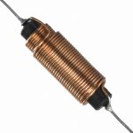
I'm nor sure if this help but I went to the Hungarian diy website and search for the inductor information, for what I see in this image I count 27 turns the core former looks like less than 10 mm in diameter probably 8 mm dia "I was close"
source of the image here:
Quad 606,707, és 909-es er?sít? tapasztalatok és hibák - Hobbielektronika.hu - online elektronikai magazin és
fórum
some translation down
"
Existing Ones doing the inductor : -the 1,5mikroH -s inductance . 7.6 mm body ( en furore wrapped ) , 1mm CuZm wire was coiled turns 27 1.51 to 1.52 will result in mikroH 4mikroH of a 10mm base 15 march to 13 march and tightly wrapped wire with 1 mm CuZm"
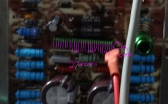
I have to come back again Terry I was looking at your board and you actually did a L4 with 27 turns but the former core I think was too small in diameter maybe increasing the core size you can get about 1.5uH you need so far a 7.6 mm core is need it if available if possible of course
source of the image here:
Quad 606,707, és 909-es er?sít? tapasztalatok és hibák - Hobbielektronika.hu - online elektronikai magazin és
fórum
some translation down
"
Existing Ones doing the inductor : -the 1,5mikroH -s inductance . 7.6 mm body ( en furore wrapped ) , 1mm CuZm wire was coiled turns 27 1.51 to 1.52 will result in mikroH 4mikroH of a 10mm base 15 march to 13 march and tightly wrapped wire with 1 mm CuZm"
I have to come back again Terry I was looking at your board and you actually did a L4 with 27 turns but the former core I think was too small in diameter maybe increasing the core size you can get about 1.5uH you need
so far a 7.6 mm core is need it if available if possible of course Attachments
Last edited:
Hi Terry. The output bridge network, including L4, provides the negative feedback which is frequency compensated so the inductor is certainly required to be close tolerance (for an inductor) which is within 5% as per the parts list. L2,3 are only 20%, so you can see the relative importance attached to the specified values. There is some argument about the final L4 value fitted not being quite on the spec. but it may still be correctly compensated in practice......Are you saying that you believe L4 could affect the low frequency of the amp?
In other words, if the inductance of L4 is incorrect or otherwise not counteracted exactly by the capacitive compensation in the input stage, the overall frequency response will be tilted. I don't actually know how much tilt would be noticeable but I have noticed that my similar design Quad 306 has a touch more bass than either a 405 or a 606 I repaired a while back. I guess you could measure frequency response well enough with a constant level sig. gen. and your 'scope by comparing response at say, 20Hz, 100Hz, 5kHz, 20kHz with a light resistive load. You could even whomp up the bass as much as you dare by playing with the feedback network

Hi Ian,
If you take a look at post #442 you will see I posted scope shots of the amp with an even voltage input at various frequencies with an 8ohm dummy load. It is set to produce about 10vac at the output. I didn't bother showing 20hz because 100hz was tilted enough to make the point. You can also see that it starts getting rounded at 10k so it pretty much shows what I am hearing which that it is voiced in the midrange area. I'm not saying that is bad, it is a nice sounding amp. I'm just reporting what I see and hear for the benefit of the thread and to see if maybe I have something that needs to be changed. Others may want to build the amp and it never hurts to have information.
Blessings, Terry
- Home
- Amplifiers
- Solid State
- Quad 909 Clone