Does movin the leads to the volume pot make any difference to the hum, I built a Quad 405 clone more than 30 years ago and found it necessary to dress the power supply DC ground and input wires together to prevent a hum loop or at least minimise its ares. The 405s have very neat wireing some of which is to prevent hum.
Stuart
Stuart
Currently, I don't use the pot. It goes direct to the RCA. Each channel is independent.
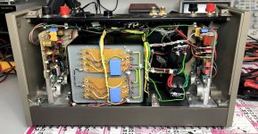
I also finished to restore my old 405.
I'll compare later. ;-)
.
I also finished to restore my old 405.
I'll compare later. ;-)
.
Attachments
Last edited:
Hi t-mink!
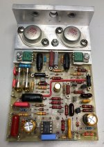
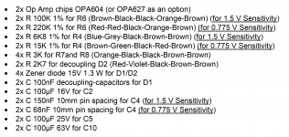
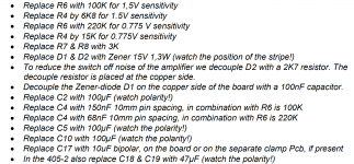
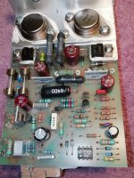
I used the values from dadaelectronics.eu. See pictures.
The Chinese SMPS used with my 405 clone is already dead. Not even two months.
I used the values from dadaelectronics.eu. See pictures.
The Chinese SMPS used with my 405 clone is already dead. Not even two months.
Attachments
Last edited:
Hi.
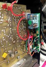
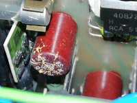
Try to replace fried resistors with bpr56 0.25R 5w one, you can find them pretty cheap direct from China.
Measure voltage unloaded before to use.
0.25R is the value I got from the same +/-45v PSU.
I think il'll do some maths but I think 6.8k/100k/150n in an inverting opamp stage give close to the same ratio than original 22k/330k/47n.
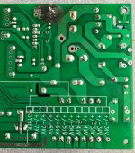
Hi I just get a pair of those green 405-2 boards to give a try.
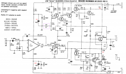
Here is the schematics I think (I checked).
What do you think of the r2 resistor if input is not connected to chassis, can I replace it with a jumper?
Here is the schematics I think (I checked).
What do you think of the r2 resistor if input is not connected to chassis, can I replace it with a jumper?
Attachments
Last edited:
Hello,
I recieved my pcb today. First, diagram did not correspond to PCB (TOP3 transistor VS TO3 implantation).
I pointed clone vs legit composants and found differents values for
R10
R2
R27/R29
C19 new
If C19 appear to protect from oscillation, I would like to check that resistances mods was only due to transistors update.
I have BDY58 or 2N3773 transistors : do I use legit or clone values ?
thanks
Attachments
I prefer to listen to my amplifiers than look at them
LIKE
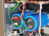
You need smoothing capacitors between the rectifier and the amplifier.
The transformer Centre Tap connects to the Input of the smoothing caps.
The output of the smoothing caps becomes the ultimate connection for the Amplifier Power Ground and the Speaker Return.
I just saw this nonsense. Please don't anybody follow it.
JI P
I just saw this nonsense. Please don't anybody follow it.
JI P
Please read the thread before you post.
Understand whats been written and yes follow it.
AndrewT's (RIP) answer was in relation to a grounding question. He is obviously talking about the ground side of the capacitors, in which case it is not nonsense, but standard wiring arrangement for a dual rail supply.
He is talking about the centre tap of the transformer, which should be grounded, and the 'input side', whatever that is, of the PSU caps: assuming he means the rail sides, they should be connected to the rectifier + and -, not directly to the transformer; and if by 'output side' he means ground he should say so.
Hi Guys
I need a bit of help. I have build Keith Snook's Mod 3 design. Made my own pcb layout and boards. The proto type works very well. I how ever are not very positive about the crowbar protection. My research/readings re this type of protection is not positive. I do have a very nice dc protection/soft start circuit that i do want to use but it needs to be connected in Paralell across the output coil and resistor normally found on most standard amp designs. Am I correct that I will need to connect this circuit across coil 2, the output side, and R20//R21, the TR2 side of Keith's Mod 3 circuit.
2 in 1
- Home
- Amplifiers
- Solid State
- QUAD 405 clone