Hello everyone, I am a great beginner in electronics, I just buy components and use them as well as possible ...
I bought a quad405 kit and I am in the process of carrying out the assembly in a beautiful box of my design ...
I have a connection problem, I understood (I think) how to connect the input of the sound + and -, the GRD ... for the output I found the OUt + on the plate but I wedged it. ..
where do I plug the output jack? there is nothing on the board!
Maybe a picture or two might help.
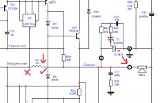
You should be able to locate the output point on the PCB by looking at a circuit diagram to identify the point electrically. There were many variations of the 405 but all have the speaker + connection going to the end of the inductor that does not connect to the output transistors.
The negative speaker connection point is the zero volt point in the main power supply.
Attachments
Hello everyone, I am a great beginner in electronics, I just buy components and use them as well as possible ...
I bought a quad405 kit and I am in the process of carrying out the assembly in a beautiful box of my design ...
I have a connection problem, I understood (I think) how to connect the input of the sound + and -, the GRD ... for the output I found the OUt + on the plate but I wedged it. ..
where do I plug the output jack? there is nothing on the board!
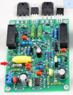
If it is an LJM QUAD405 or QUAD405-2 I could help. Can you identify your board? Just post a photo of it or the listing photo from where you bought it.
For example, on the LJM QUAD405-2 version (pictured) the output is the red tab. The tab marked ground goes to your rectifier filter board. The speaker return also goes to your rectifier filter board.
But if you post the photo of the version you have someone will be able to show you the correct connections.
I assume you have a speaker protection board?
Attachments
Good morning and thank you for your answers,
So at least that goes to the speaker I must connect the jack directly to the output of the power supply, with a wire per jack I suppose
https://ae01.alicdn.com/kf/H6aacea0349ad48adaa49e38f3b0bcec1X.jpg
So at least that goes to the speaker I must connect the jack directly to the output of the power supply, with a wire per jack I suppose
https://ae01.alicdn.com/kf/H6aacea0349ad48adaa49e38f3b0bcec1X.jpg
not yet, what do you advise me?"I assume you have a speaker protection board?"
i found this
AIYIMA – carte de Protection de haut parleur UPC1237 900W 2.0, 2 canaux AC 85 265V DC, retardateur de mise sous tension pour amplificateur de haut parleur | AliExpress
Good morning and thank you for your answers,
So at least that goes to the speaker I must connect the jack directly to the output of the power supply, with a wire per jack I suppose
Yes, the speaker negative (or speaker return) goes to the 0v point of the power supply.
The speaker positive output is clearly marked on that board. There is also a 'ground' terminal on the board that must be connected correctly.
You have to be sure or else you could damage the board or speaker.
I followed your advice and put the sector, everything looks good at first glance, no big black smoke or flash the diodes of the rectifier filter board are on
it seems to me that I still have problems to solve ...
I think I correctly connected the cards, but it does not fill up or very can the sound.
I have +55 and -55 v at the output of the rectify filter board, it must be there or I messed up ...
I plug in a +55 and GND on one card and -55v and GND on the other card?
Denis, it sounds like you need to research how it all works and connects up ")
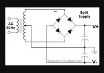
Your power supply should look something like this. V+ will be plus 55 volt and V- will be negative 55 volt. The centre point with the ground symbol is the ground or zero volt point.
Each amp board needs all these connecting correctly to it. The ground connection on the board looks to be needed twice, one connection to the ground tag and one to the input ground.
It is vitally important you get these right or the amp could be damaged.
Attachments
Thanks for the designs
I redid another diagram with all the connections and how I connected them
Google Drive: Sign-in
I redid another diagram with all the connections and how I connected them
Google Drive: Sign-in
Last edited:
Attachments


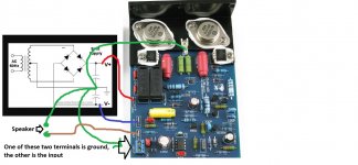
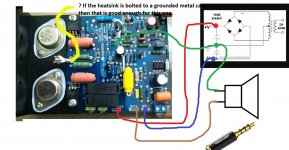
That is not right, but one important difference I can see in your picture is an additional tag on the board itself. That wasn't obvious in the earlier picture. Is that ground ?????
VCC+ goes to the +50 volt supply. You have this one wrong.
VEE- goes to the -50 volt supply. You have this one wrong.
The speaker wiring is correct
The additional ground tag (if that is what it is) would be correct
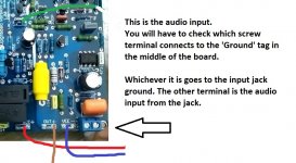
The ground to the input jack should be altered. Check if one of those terminals goes to the 'new' ground tag on the board. If it does then you wire the jack input ground to the screw terminal that is ground.
The audio input itself goes to the other screw terminal. In other words you wire the input to the screw terminals. Just make sure you know which terminal is ground.
VCC+ goes to the +50 volt supply. You have this one wrong.
VEE- goes to the -50 volt supply. You have this one wrong.
The speaker wiring is correct
The additional ground tag (if that is what it is) would be correct
The ground to the input jack should be altered. Check if one of those terminals goes to the 'new' ground tag on the board. If it does then you wire the jack input ground to the screw terminal that is ground.
The audio input itself goes to the other screw terminal. In other words you wire the input to the screw terminals. Just make sure you know which terminal is ground.
Here are the photos of my box I made it entirely with recycled materials, I still have to find perforated sheet metal for the cover
How to attach images to your posts.
How to attach images to your posts.
Attachments
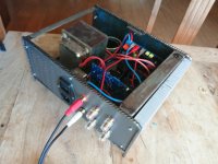
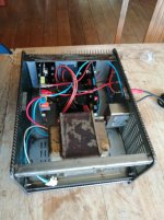
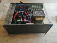
Well that looks pretty good but you must be 100% certain you have it all wired correctly.
I would advise you use a bulb tester to power it all up (only when you are sure it is correct) and you should check there is no DC voltage across the speaker terminals before connecting a speaker.
but you must be 100% certain you have it all wired correctly.I would advise you use a bulb tester to power it all up (only when you are sure it is correct) and you should check there is no DC voltage across the speaker terminals before connecting a speaker.

- Home
- Amplifiers
- Solid State
- QUAD 405 clone