Do you have a link to the files? I am new to Github....Hello,
Kicad files and Gerber files uploaded to the Github repository.
Have fun.
Stef.
Hello,
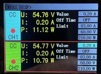
I did a test at 60V input 200mA load with an electronic load. I can't measure. The device full of MOSFET disrupts the measurement.
I need to see if I can find power resistors that would at least allow me to test the ripple at 200mA.
I'll do heat and voltage loss tests based on amperage instead.
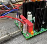
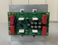
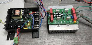
At 200mA, the SK104-50 heatsinks are at 30/32°C after 1 hour (room at 20°C).
The bet of a board which holds 200mA with its heatsinks on the PCB seems to have been met. I still have to have some room (15W in theory). I will push to stabilize them around 40°C.
Stef.
I did a test at 60V input 200mA load with an electronic load. I can't measure. The device full of MOSFET disrupts the measurement.
I need to see if I can find power resistors that would at least allow me to test the ripple at 200mA.
I'll do heat and voltage loss tests based on amperage instead.
At 200mA, the SK104-50 heatsinks are at 30/32°C after 1 hour (room at 20°C).
The bet of a board which holds 200mA with its heatsinks on the PCB seems to have been met. I still have to have some room (15W in theory). I will push to stabilize them around 40°C.
Stef.
Attachments
")
Hello,
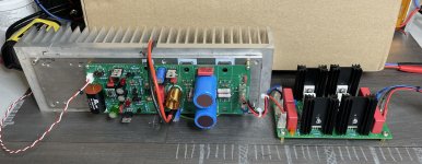
After several days of operation with an amplifier board, the SIgma board is good for service. I didn't find any problem with it. Everything seems to work well both when measuring with a scope and when listening.
Happy experimenting if you decide to build it.
Stef.
After several days of operation with an amplifier board, the SIgma board is good for service. I didn't find any problem with it. Everything seems to work well both when measuring with a scope and when listening.
Happy experimenting if you decide to build it.
Stef.
Attachments
Hello,
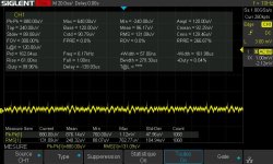
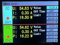
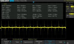
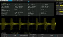
If you increase the voltage difference you can lower it further. On the first measurement, I was just on the verge of stalling.
In the first measurement, I was at 60V input and 54V output.
If I go to 62V input for 54V output. Measurement is better. I think as you continue to increase the difference, the measurement will get even better. You just have to find the right position neither too much nor too little depending on the power supply in front and the consumption / voltage behind.
Stef.
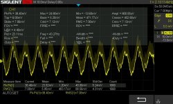
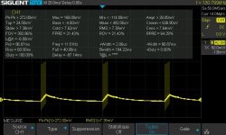
EDIT: you have to play around with the settings on the SMPS and on the Sigma.
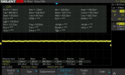
In the second curve. 58V at input (mini on SMPS) and come out at 53V, diff 5V and I got 14.20pp / 1.23mV RMS.
If you increase the voltage difference you can lower it further. On the first measurement, I was just on the verge of stalling.
In the first measurement, I was at 60V input and 54V output.
If I go to 62V input for 54V output. Measurement is better. I think as you continue to increase the difference, the measurement will get even better. You just have to find the right position neither too much nor too little depending on the power supply in front and the consumption / voltage behind.
Stef.
EDIT: you have to play around with the settings on the SMPS and on the Sigma.
In the second curve. 58V at input (mini on SMPS) and come out at 53V, diff 5V and I got 14.20pp / 1.23mV RMS.
Attachments
Last edited:
- Home
- Amplifiers
- Power Supplies
- Q17 Sigma22 Regulated Ultrastable Ultralow Noise Linear Power Supply +-50/60Vcc